MA240017 Microchip Technology, MA240017 Datasheet - Page 150
MA240017
Manufacturer Part Number
MA240017
Description
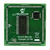
MODULE PLUG-IN PIC24F16KA102 PIM
Manufacturer
Microchip Technology
Series
PIC®r
Specifications of MA240017
Accessory Type
Plug-In Module (PIM) - PIC24F16KA102
Product
Microcontroller Modules
Data Bus Width
16 bit
Core Processor
PIC24F16KA102
Operating Supply Voltage
3 V to 3.6 V
Development Tools By Supplier
Integrated Development Environment, Assembler, ANSI C Compiler
Processor Series
PIC24F
Silicon Manufacturer
Microchip
Core Architecture
PIC
Core Sub-architecture
PIC24
Silicon Core Number
PIC24F
Silicon Family Name
PIC24FxxKAxx
Lead Free Status / RoHS Status
Lead free / RoHS Compliant
For Use With/related Products
Explorer 16 (DM240001 or DM240002)
For Use With
DM240001 - BOARD DEMO PIC24/DSPIC33/PIC32
Lead Free Status / Rohs Status
Lead free / RoHS Compliant
Available stocks
Company
Part Number
Manufacturer
Quantity
Price
Company:

Part Number:
MA240017
Manufacturer:
MICROCHIP
Quantity:
12 000


PIC24F16KA102 FAMILY
REGISTER 18-2:
DS39927B-page 148
bit 15
bit 7
Legend:
R = Readable bit
-n = Value at POR
bit 15,13
bit 14
bit 12
bit 11
bit 10
bit 9
bit 8
bit 7-6
URXISEL1
UTXISEL1
R/W-0
R/W-0
UTXISEL<1:0>: Transmission Interrupt Mode Selection bits
11 = Reserved; do not use
10 = Interrupt when a character is transferred to the Transmit Shift Register (TSR), and as a result,
01 = Interrupt when the last character is shifted out of the Transmit Shift Register; all transmit operations
00 = Interrupt when a character is transferred to the Transmit Shift Register (this implies there is at
UTXINV: IrDA
If IREN = 0:
1 = UxTX Idle ‘0’
0 = UxTX Idle ‘1’
If IREN = 1:
1 = UxTX Idle ‘1’
0 = UxTX Idle ‘0’
Unimplemented: Read as ‘0’
UTXBRK: Transmit Break bit
1 = Send Sync Break on next transmission – Start bit, followed by twelve ‘0’ bits, followed by Stop bit;
0 = Sync Break transmission disabled or completed
UTXEN: Transmit Enable bit
1 = Transmit enabled, UxTX pin controlled by UARTx
0 = Transmit disabled, any pending transmission is aborted and buffer is reset. UxTX pin controlled by
UTXBF: Transmit Buffer Full Status bit (read-only)
1 = Transmit buffer is full
0 = Transmit buffer is not full, at least one more character can be written
TRMT: Transmit Shift Register Empty bit (read-only)
1 = Transmit Shift Register is empty and transmit buffer is empty (the last transmission has completed)
0 = Transmit Shift Register is not empty, a transmission is in progress or queued
URXISEL<1:0>: Receive Interrupt Mode Selection bits
11 = Interrupt is set on RSR transfer, making the receive buffer full (i.e., has 4 data characters)
10 = Interrupt is set on RSR transfer, making the receive buffer 3/4 full (i.e., has 3 data characters)
0x = Interrupt is set when any character is received and transferred from the RSR to the receive buffer.
URXISEL0
UTXINV
R/W-0
R/W-0
cleared by hardware upon completion
the PORT register.
the transmit buffer becomes empty
are completed
least one character open in the transmit buffer)
Receive buffer has one or more characters.
UxSTA: UARTx STATUS AND CONTROL REGISTER
®
C = Clearable bit
HS = Hardware Settable bit
W = Writable bit
‘1’ = Bit is set
Encoder Transmit Polarity Inversion bit
UTXISEL0
ADDEN
R/W-0
R/W-0
R-1, HSC
RIDLE
U-0
—
Preliminary
HC = Hardware Clearable bit
HSC = Hardware Settable/Clearable bit
U = Unimplemented bit, read as ‘0’
‘0’ = Bit is cleared
R/W-0, HC
R-0, HSC
UTXBRK
PERR
R-0, HSC
UTXEN
R/W-0
FERR
© 2009 Microchip Technology Inc.
x = Bit is unknown
R/C-0, HS
R-0, HSC
UTXBF
OERR
R-1, HSC
R-0, HSC
URXDA
TRMT
bit 8
bit 0
Related parts for MA240017
Image
Part Number
Description
Manufacturer
Datasheet
Request
R

Part Number:
Description:
Manufacturer:
Microchip Technology Inc.
Datasheet:
Part Number:
Description:
Manufacturer:
Microchip Technology Inc.
Datasheet:
Part Number:
Description:
Manufacturer:
Microchip Technology Inc.
Datasheet:
Part Number:
Description:
Manufacturer:
Microchip Technology Inc.
Datasheet:
Part Number:
Description:
Manufacturer:
Microchip Technology Inc.
Datasheet:
Part Number:
Description:
Manufacturer:
Microchip Technology Inc.
Datasheet:
Part Number:
Description:
Manufacturer:
Microchip Technology Inc.
Datasheet:
Part Number:
Description:
Manufacturer:
Microchip Technology Inc.
Datasheet: