MA240017 Microchip Technology, MA240017 Datasheet - Page 121
MA240017
Manufacturer Part Number
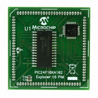
MA240017
Description
MODULE PLUG-IN PIC24F16KA102 PIM
Manufacturer
Microchip Technology
Series
PIC®r
Specifications of MA240017
Accessory Type
Plug-In Module (PIM) - PIC24F16KA102
Product
Microcontroller Modules
Data Bus Width
16 bit
Core Processor
PIC24F16KA102
Operating Supply Voltage
3 V to 3.6 V
Development Tools By Supplier
Integrated Development Environment, Assembler, ANSI C Compiler
Processor Series
PIC24F
Silicon Manufacturer
Microchip
Core Architecture
PIC
Core Sub-architecture
PIC24
Silicon Core Number
PIC24F
Silicon Family Name
PIC24FxxKAxx
Lead Free Status / RoHS Status
Lead free / RoHS Compliant
For Use With/related Products
Explorer 16 (DM240001 or DM240002)
For Use With
DM240001 - BOARD DEMO PIC24/DSPIC33/PIC32
Lead Free Status / Rohs Status
Lead free / RoHS Compliant
Available stocks
Company
Part Number
Manufacturer
Quantity
Price
Company:

Part Number:
MA240017
Manufacturer:
MICROCHIP
Quantity:
12 000


14.0
The input capture module is used to capture a timer
value from one of two selectable time bases upon an
event on an input pin.
The input capture features are quite useful in
applications requiring frequency (Time Period) and
pulse measurement. Figure 14-1 depicts a simplified
block diagram of the input capture module.
FIGURE 14-1:
© 2009 Microchip Technology Inc.
Note:
IC1 Pin
INPUT CAPTURE
This data sheet summarizes the features
of this group of PIC24F devices. It is not
intended to be a comprehensive reference
source. For more information on Input
Capture, refer to the “PIC24F Family
Reference Manual”, Section 15. “Input
Capture” (DS39701).
Prescaler
(1, 4, 16)
Counter
3
INPUT CAPTURE BLOCK DIAGRAM
System Bus
IC1CON
ICM<2:0> (IC1CON<2:0>)
ICOV, ICBNE (IC1CON<4:3>)
Mode Select
Edge Detection Logic
Clock Synchronizer
ICI<1:0>
Preliminary
PIC24F16KA102 FAMILY
(in IFSn Register)
Set Flag IC1IF
Interrupt
Logic
The PIC24F16KA102 family devices have one input
capture channel. The input capture module has
multiple operating modes, which are selected via the
IC1CON register. The operating modes include:
• Capture timer value on every falling edge of input
• Capture timer value on every rising edge of input
• Capture timer value on every 4
• Capture timer value on every 16
• Capture timer value on every rising and every
• Device wake-up from capture pin during CPU
The input capture module has a four-level FIFO buffer.
The number of capture events required to generate a
CPU interrupt can be selected by the user.
applied at the IC1 pin
applied at the IC1 pin
input applied at the IC1 pin
input applied at the IC1 pin
falling edge of input applied at the IC1 pin
Sleep and Idle modes
Logic
FIFO
R/W
From 16-Bit Timers
TMRy TMRx
1
IC1BUF
16
th
th
rising edge of
0
DS39927B-page 119
rising edge of
16
(IC1CON<7>)
ICTMR
Related parts for MA240017
Image
Part Number
Description
Manufacturer
Datasheet
Request
R

Part Number:
Description:
Manufacturer:
Microchip Technology Inc.
Datasheet:
Part Number:
Description:
Manufacturer:
Microchip Technology Inc.
Datasheet:
Part Number:
Description:
Manufacturer:
Microchip Technology Inc.
Datasheet:
Part Number:
Description:
Manufacturer:
Microchip Technology Inc.
Datasheet:
Part Number:
Description:
Manufacturer:
Microchip Technology Inc.
Datasheet:
Part Number:
Description:
Manufacturer:
Microchip Technology Inc.
Datasheet:
Part Number:
Description:
Manufacturer:
Microchip Technology Inc.
Datasheet:
Part Number:
Description:
Manufacturer:
Microchip Technology Inc.
Datasheet: