MA240017 Microchip Technology, MA240017 Datasheet - Page 137
MA240017
Manufacturer Part Number
MA240017
Description
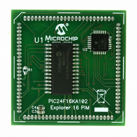
MODULE PLUG-IN PIC24F16KA102 PIM
Manufacturer
Microchip Technology
Series
PIC®r
Specifications of MA240017
Accessory Type
Plug-In Module (PIM) - PIC24F16KA102
Product
Microcontroller Modules
Data Bus Width
16 bit
Core Processor
PIC24F16KA102
Operating Supply Voltage
3 V to 3.6 V
Development Tools By Supplier
Integrated Development Environment, Assembler, ANSI C Compiler
Processor Series
PIC24F
Silicon Manufacturer
Microchip
Core Architecture
PIC
Core Sub-architecture
PIC24
Silicon Core Number
PIC24F
Silicon Family Name
PIC24FxxKAxx
Lead Free Status / RoHS Status
Lead free / RoHS Compliant
For Use With/related Products
Explorer 16 (DM240001 or DM240002)
For Use With
DM240001 - BOARD DEMO PIC24/DSPIC33/PIC32
Lead Free Status / Rohs Status
Lead free / RoHS Compliant
Available stocks
Company
Part Number
Manufacturer
Quantity
Price
Company:

Part Number:
MA240017
Manufacturer:
MICROCHIP
Quantity:
12 000


17.0
The Inter-Integrated Circuit (I
interface
peripheral or microcontroller devices. These peripheral
devices may be serial data EEPROMs, display drivers,
A/D Converters, etc.
The I
• Independent master and slave logic
• 7-bit and 10-bit device addresses
• General call address, as defined in the I
• Clock stretching to provide delays for the
• Both 100 kHz and 400 kHz bus specifications
• Configurable address masking
• Multi-Master modes to prevent loss of messages
• Bus Repeater mode, allowing the acceptance of
• Automatic SCL
Figure 17-1 illustrates a block diagram of the module.
17.1
The I
with peripheral multiplexing, the I2C1 module in 28-pin
devices can be reassigned to the alternate pins,
designated as SCL1 and SDA1 during device
configuration.
Pin assignment
Configuration bit. Programming this bit (= 0) multiplexes
the module to the SCL1 and SDA1 pins.
© 2009 Microchip Technology Inc.
Note:
processor to respond to a slave data request
in arbitration
all messages as a slave regardless of the address
2
2
C module supports these features:
C module is tied to a fixed pin. To allow flexibility
INTER-INTEGRATED CIRCUIT
(I
Pin Remapping Options
2
useful
This data sheet summarizes the features
of this group of PIC24F devices. It is not
intended to be a comprehensive reference
source. For more information on the
Inter-Integrated
“PIC24F
Section 24. “Inter-Integrated Circuit
(I
C™)
2
C™)” (DS39702).
is controlled by the I2C1SEL
for
Family
communicating
Circuit,
2
C™) module is a serial
Reference
refer
2
C protocol
with
Manual”,
to
other
the
Preliminary
PIC24F16KA102 FAMILY
17.2
The details of sending a message in Master mode
depends on the communications protocol for the device
being communicated with. Typically, the sequence of
events is as follows:
1.
2.
3.
4.
5.
6.
7.
8.
9.
10. Wait for and verify an Acknowledge from the
11. Enable master reception to receive serial
12. Generate an ACK or NACK condition at the end
13. Generate a Stop condition on SDA1 and SCL1.
Assert a Start condition on SDA1 and SCL1.
Send the I
with a write indication.
Wait for and verify an Acknowledge from the
slave.
Send the first data byte (sometimes known as
the command) to the slave.
Wait for and verify an Acknowledge from the
slave.
Send the serial memory address low byte to the
slave.
Repeat steps 4 and 5 until all data bytes are
sent.
Assert a Repeated Start condition on SDA1 and
SCL1.
Send the device address byte to the slave with
a read indication.
slave.
memory data.
of a received byte of data.
Communicating as a Master in a
Single Master Environment
2
C device address byte to the slave
DS39927B-page 135
Related parts for MA240017
Image
Part Number
Description
Manufacturer
Datasheet
Request
R

Part Number:
Description:
Manufacturer:
Microchip Technology Inc.
Datasheet:
Part Number:
Description:
Manufacturer:
Microchip Technology Inc.
Datasheet:
Part Number:
Description:
Manufacturer:
Microchip Technology Inc.
Datasheet:
Part Number:
Description:
Manufacturer:
Microchip Technology Inc.
Datasheet:
Part Number:
Description:
Manufacturer:
Microchip Technology Inc.
Datasheet:
Part Number:
Description:
Manufacturer:
Microchip Technology Inc.
Datasheet:
Part Number:
Description:
Manufacturer:
Microchip Technology Inc.
Datasheet:
Part Number:
Description:
Manufacturer:
Microchip Technology Inc.
Datasheet: