KP-FSD2 Panduit Corp, KP-FSD2 Datasheet - Page 767
KP-FSD2
Manufacturer Part Number
KP-FSD2
Description
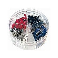
KIT FERRULE INS DIN AWG22-14
Manufacturer
Panduit Corp
Series
Pan-Term®r
Type
Ferrule Kitr
Datasheet
1.KP-FSD1.pdf
(1040 pages)
Specifications of KP-FSD2
Kit Type
Ferrule - Wire End
Values
400 pcs - Assorted Insulated 22 ~ 14 AWG Ferrules
Where Used
To terminate stranded wire for insertion into terminal blocks
Lead Free Status / Rohs Status
Lead free / RoHS Compliant


For Use with Stranded Aluminum or Copper Code Conductors
Type LAM3D
• Triple barrel provides termination of three conductors
• Made from high strength, extruded aluminum alloy to provide
• Tin-plated to inhibit corrosion
• Wide wire range-taking capability minimizes inventory requirements
• Inspection window to visually assure full conductor insertion
◆ LAM3D3/0-12-3Y
◆ LAM3D250-12-1Y
◆ LAM3D350-12-1Y
◆ LAM3LD600-12-1
◆ LAM3LD1000-121Y
premium electrical and mechanical performance
The use of Panduit oxide inhibiting joint compound (CMP-100) is recommended for pad to pad and conductor connections. See page D2.155.
◆NEMA hole sizes and spacing.
Part Number
Four-Hole, Three-Barrel Lug
Figure
No.
1
1
1
2
2
#6 AWG – 250 kcmil
#6 AWG – 350 kcmil
#2 AWG – 600 kcmil
500 kcmil – 1000 kcmil
#6 AWG – 3/0 AWG
Size Range
Conductor
For technical assistance in the U.S., call 866-405-6654 (outside the U.S., see inside back cover for directory)
Stud Hole
ELECTRICAL SOLUTIONS
Size
(In.)
1/2
1/2
1/2
1/2
1/2
Stud Hole
Spacing
• Plated steel or aluminum set screw provides high strength, durable
• LAM3LD connector is provided with dual set screws to allow
• For use up to 600 V and temperature rated 90°C
• Available with NEMA hole sizes and spacing
1.75
1.75
1.75
1.75
1.75
SPACING
(In.)
electrical contact between conductor and connector
premium clamping of conductor to connector for heavy
duty applications
HOLE
T
Hex Key
SPACING
Figure 1
HOLE
Size
5/16
5/16
(In.)
P
1/4
3/8
1/2
L
4.25
4.25
4.50
5.50
6.19
L
W
H
2.81
3.00
3.50
4.32
5.27
W
Figure Dimensions
SPACING
HOLE
T
(In.)
1.19
1.19
1.38
1.50
1.88
H
SPACING
HOLE
Figure 2
P
0.31
0.31
0.31
0.38
0.56
T
L
3.25
3.25
3.25
3.25
3.44
P
W
H
Pkg.
Std.
Qty.
3
1
1
1
1
D2.145
Management
Identification
Accessories
Connectors
Connectors
Grounding
Pre-Printed
& Write-On
Protection
Permanent
Solutions
Cable Ties
Terminals
Lockout/
Overview
Steel Ties
& Safety
Stainless
Raceway
Abrasion
Labeling
Systems
Surface
Markers
Tagout
System
Wiring
Labels
Power
Cable
Cable
Index
Duct
E5.
B1.
B2.
B3.
D1.
D2.
D3.
C1.
C2.
C3.
C4.
E1.
E2.
E3.
E4.
A.
F.