KP-FSD2 Panduit Corp, KP-FSD2 Datasheet - Page 622
KP-FSD2
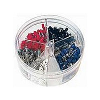
Manufacturer Part Number
KP-FSD2
Description
KIT FERRULE INS DIN AWG22-14
Manufacturer
Panduit Corp
Series
Pan-Term®r
Type
Ferrule Kitr
Datasheet
1.KP-FSD1.pdf
(1040 pages)
Specifications of KP-FSD2
Kit Type
Ferrule - Wire End
Values
400 pcs - Assorted Insulated 22 ~ 14 AWG Ferrules
Where Used
To terminate stranded wire for insertion into terminal blocks
Lead Free Status / Rohs Status
Lead free / RoHS Compliant


Management
Identification
Accessories
Connectors
Connectors
Protection
Grounding
Pre-Printed
& Write-On
Permanent
Solutions
Overview
Cable Ties
Steel Ties
Terminals
Lockout/
Stainless
& Safety
Raceway
Abrasion
Labeling
Systems
Markers
Surface
Tagout
System
Wiring
Power
Labels
Cable
Cable
Index
Duct
E5.
B1.
B2.
B3.
D1.
D2.
D3.
C1.
C2.
C3.
C4.
E1.
E2.
E3.
E4.
A.
F.
D2.0
Compression Connector Reference Information
Management
Identification
Overview
Cable Ties
Accessories
Steel Ties
Protection
Terminals
Connectors
Grounding
Connectors
Pre-Printed
& Write-On
Permanent
Lockout/
& Safety
Solutions
System
Stainless
Surface
Raceway
Abrasion
Labeling
Systems
Markers
Tagout
Cable
Wiring
Duct
Cable
Power
Labels
Index
D3.58
B1.
B2.
B3.
C1.
C2.
C3.
C4.
D1.
D2.
D3.
E1.
E2.
E3.
E4.
E5.
A.
F.
Selection Guide – P
for Copper Code Conductor
For Use with Stranded Copper Conductors
Type LCC-00
• Long barrel maximizes number of crimps and provides premium
• Color coded barrels marked with PANDUIT and specified
• Enclosed barrel prevents corrosive material from entering barrel
‡See pages «X,2,CR-PGC-TolSlct-LCB1», «X,2,CR-PGC-TolSlct-LCB2» for tool and die information.
**Consult cable manufacturer for voltage stress relief instructions with applications greater than 2000 V.
➀The CT-1700 and CT-1701 crimp die pockets are integrated into the tool frame.
➂CD-920 dies can be used with CT-940CH and CT-2940 tools with CD-940-DA
adapter.
Part Number
LCC8-00-L
LCC6-00-L
LCC4-00-L
LCC2-00-Q
LCC1-00-E
LCC1/0-00-X
LCC2/0-00-X
LCC3/0-00-X
LCC4/0-00-X
LCC250-00-X
LCC300-00-X
LCC350-00-X
LCC400-00-6
LCC500-00-6
LCC600-00-6
LCC750-00-6
LCC1000-00-3
How to read
this chart
For LCB6 lug
and CT-2001
crimping tool
Panduit
Part
Number
L = Lug
S = Splice
LCB10
LCC10
LCB8
LCBN8
LCC8
LCCN8
SCL8
LCB6
LCBN6
LCC6
LCCN6
SCL6
LCB4
LCBN4
LCC4
LCCN4
SCL4
LCB2
LCBN2
LCC2
LCCN2
SCL2
LCB1
LCBN1
LCC1
LCCN1
SCL1
LCB1/0
LCBN1/0
LCC1/0
LCCN1/0
SCL1/0
LCB2/0
LCBN2/0
LCC2/0
LCCN2/0
SCL2/0
LCB3/0
LCBN3/0
LCC3/0
LCCN3/0
SCL3/0
LCB4/0
LCBN4/0
LCC4/0
LCCN4/0
SCL4/0
LCB250
LCBN250
LCC250
LCCN250
SLC250
wire pull-out strength and electrical performance
competitor die index numbers for proper crimp die selection
when used in harsh environments
For use with
Conductors
Copper
Image to
come
Image to
come
Code Conductor, Blank Tongue, Long Barrel Lug (continued)
:
AWG STR,
Color
Code
#14 – #10
#12 – #10
#8 AWG
#6 AWG
#2 AWG
#1 AWG
1/0 AWG
2/0 AWG
3/0 AWG
4/0 AWG
250 kcmil
Number of
#4 – #3
#2 AWG
Wire
AWG
AWG
Crimps
Std.
Size
STR,
SOL
SOL
Installation Tooling and Die Selections for:
Types LCB, LCBN, LCC, LCCN and SCL
Connector
Figure
One-Hole Lugs
Two-Hole Lugs
Parallel Splices
Die Part Number
Metric Splices
No.
1
2
2
1
1
1
1
1
1
1
1
1
1
1
1
1
1
CD-2001-6
Butt Splices
Metric Lugs
Metric Lugs
Blue P24
T Splices
One-Hole
Two-Hole
(2)
Length
1-11/16
Die Index
Strip
1-1/16
1-1/8
1-1/8
1-1/4
1-7/16
1-3/8
1-1/2
1-3/8
1-9/16
1-1/2
1-9/16
1-1/2
1-5/8
1-5/8
Number
Wire
(In.)
9/16
Conductor Size
3/4
#4 – #3 AWG
STR, #2 AWG
1000 kcmil
#8 AWG
#6 AWG
#2 AWG
#1 AWG
1/0 AWG
2/0 AWG
3/0 AWG
4/0 AWG
250 kcmil
300 kcmil
350 kcmil
400 kcmil
500 kcmil
600 kcmil
750 kcmil
Copper
SOL
CT-1570 CT-1701➀ CT-1700➀
AN
12-10
Panduit (See Compression Connector Tools Selection Guide,
(2)
—
—
—
—
—
—
—
—
—
—
-L
For technical assistance in the U.S., call 866-405-6654 (outside the U.S., see inside back cover for directory)
W
T
For technical assistance in the U.S., call 866-405-6654 (outside the U.S., see inside back cover for directory)
UG
.60
.75
.75
.75
.75
.80
.85
.96
1.06
1.17
1.19
1.28
1.39
1.54
1.70
1.89
2.17
Die Part Number/Color Code and Die Index Number/(Number Of Crimps)
P10
Figure Dimensions (In.)
W
(2)
—
—
—
—
—
—
—
—
—
—
™
Copper Compression Connectors
Standard barrel with
.70
1.13
1.13
1.16
1.36
1.44
1.50
1.50
1.56
1.60
2.23
2.23
2.29
2.49
2.68
2.87
2.99
Blue P24
Barrel Style
Standard barrel with
B
Red P21
inspection window
inspection window
inspection window
inspection window
inspection window
inspection window
inspection window
Brown
Green
Short barrel with
Long barrel with
Long barrel with
Standard barrel
ELECTRICAL SOLUTIONS
Gray
P29
P33
P37
Long barrel no
Long barrel no
—
(3)
(3)
(3)
(3)
(4)
—
—
—
—
—
ELECTRICAL SOLUTIONS
Short barrel
Long barrel
ELECTRICAL SOLUTIONS
.05
.16
.16
.08
.09
.12
.13
.13
.14
.14
.16
.17
.18
.22
.26
.26
.32
T
Pages D3.30 – D3.32)
CD-720-1
Red P21
CD-720-1
Blue P24
CD-720-1
Gray P29
CD-720-1
CD-720-2
CD-720-2
Pink P42
CD-720-2
CD-720-2
CD-720-3
CD-720-3
CT-720
Orange
Figure 1
Brown
Green
Black
Purple
Yellow
P33
P37
P45
P50
P54
P62
—
(2)
(2)
(2)
(2)
(2)
(2)
(3)
(3)
(3)
(4)
2.75
5.00
5.06
4.51
4.74
4.86
4.98
5.03
5.13
5.23
5.94
5.99
6.10
6.36
6.63
7.04
7.29
L
L
• Tin plated to inhibit corrosion
• UL Recognized and CSA Certified to 35 KV** and temperature
CT-930LPCH➅,
rated to 90°C when crimped with PANDUIT and specified
competitor crimping tools and dies
PANDUIT
CT-2930/LE,
CT-940CH➂,
CT-2940/L➂,
CT-2940/LE➂
Orange P50
CD-920-250
CT-920CH,
CT-930CH,
CT-2930/L,
CT-2940➂,
Brown P33
Green P37
CD-920-1/0
CD-920-2/0
CD-920-3/0
CD-920-4/0
Purple P54
Yellow P62
➄Maximum size: 500 kcmil lugs and 250 kcmil splices.
➅Maximum size: 250 kcmil lugs and splices. No extended wire range.
pCode
Brown
Green
Orange
Purple
Yellow
Brown
Green
CT-2920,
CT-2930,
CT-2931,
CD-920-8
Red P21
CD-920-6
Blue P24
CD-920-4
Gray P29
CD-920-2
CD-920-1
Pink P42
Black P45
Color
Blue
Gray
Pink
Black
White
Blue
Black
White
CT-920,
CT-930,
Red
Red
Type
LCAS
LCAS-H 45° bent
LCAS-F 90° bent
LCA
LCA-H 45° bent
LCA-F 90° bent
LCAN narrow tongue
LCA-00 blank tongue
LCB
LCB-H 45° bent
LCB-F 90° bent
LCBH with corona relief taper
LCB-W
LCB-WH 45° bent
LCB-WF 90° bent
LCD
LCD-H 45° bent
LCD-F 90° bent
LCDN narrow tongue
LCDN-H 45° bent narrow tongue
LCDN-F 90° bent narrow tongue
LCD-00 blank tongue
LCC
LCC-H 45° bent
LCC-F 90° bent
LCCH with corona relief taper
LCC-00 blank tongue
LCC-W
LCC-WH 45° bent
LCC-WF 90° bent
LCCN-W narrow tongue
LCC-00W blank tongue
SCSS
SCS
SCL
SCH with corona relief chamfer
SCT
PSC
LCMA
LCMD
SCMS
—
(1)
(1)
(1)
(1)
(1)
(2)
(3)
(3)
(3)
(3)
SCSS
B
PANDUIT
Die Index
CT-980LPCH➅,
#4 – #2 AWG
#6 – #2 AWG
#6 – #1 AWG
#6 – 1/0 AWG
#4 – 2/0 AWG
#2 – 3/0 AWG
#1 – 4/0 AWG
P106
P125
CT-2980/LE,
Wire Range
No.
P21
P24
P29
P33
P37
P42
P45
P50
P54
P62
P66
P71
P76
P87
P94
CT-980CH,
CT-2950➄,
CT-2980/L,
Extended
SOL Only
1/0 AWG –
250 kcmil
Uni-Die
CT-980,
CT-2980,
CT-2981,
#2 AWG
(1)
(1)
(1)
(2)
(2)
(2)
(2)
(3)
—
—
—
™
T
W
Die Index
Burndy
Figure 2: Two-Piece Brazed Tongue
No.‡
CT-2001/L,
CT-2001/LE,
CT-2002/L,
CD-2001-8
CD-2001-6
CD-2001-4
CD-2001-2
Brown P33
CD-2001-1
Orange P50
Purple P54
49
10
11
12
13
14
15
16
17
18
19
20
22
24
27
CT-3001/E
Gray P29
Green P37
CD-2001-
CD-2001-
Black P45
CD-2001-
CD-2001-
Yellow P62
7
8
CT-2001,
CT-2002,
CT-3001,
Red P21
Blue P24
Pink P42
CD-2001-
—
(2)
(2)
(2)
(2)
(2)
1/0
(2)
2/0
(3)
3/0
(3)
4/0
(3)
250
(3)
Construction
Die Index
TBM20S,
TBM25S TBM5
Gray 29
D2.46, D2.47, D2.48
D2.49, D2.50, D2.51
D2.52, D2.53, D2.54
T&B
No.‡
Red 21
Blue 24
Brown
21
24
29
33
37
42
45
50
54
62
66
71
76
87
94
106
125
(3)
(3)
(3)
(3)
Prime items appear in BOLD.
Pg.
—
33
—
—
—
—
—
—
Thomas & Betts
L
Page Number
D2.10, D2.11
D2.12, D2.13
D2.14, D2.15
D2.16, D2.17
D2.18, D2.19
D2.21, D2.22
D2.23, D2.24
D2.25, D2.26
D2.30, D2.31
D2.32, D2.33
D2.34, D2.35
D2.40, D2.41
D2.42, D2.43
D2.44, D2.45
Brown
Green
Orange
Purple
Yellow
Red
Blue
Gray
Pink
Black
—
21
(1)
24
(1)
29
(1)
33
(1)
37
(1)
42
(2)
45
(3)
50
(3)
54
(3)
62
(4)
D2.6, D2.7
D2.8, D2.9
Wire Strip
Length
1 11/16
2 15/16
1 1/8
1 1/8
1 1/4
1 7/16
1 1/2
1 9/16
1 9/16
1 5/8
2 5/16
2 5/16
2 3/8
2 9/16
2 3/4
3 1/16
(In.)
3/4
TBM6S,
Code
D2.XX
D2.XX
D2.XX
TBM6,
25000,
TBM8
Brown
Green
Orange
Purple
Yellow
D2.20
D2.29
D2.27
D2.28
D2.28
D2.36
D2.37
D2.38
D2.39
D2.55
D2.56
D2.54
D2.57
D2.58
D2.59
D2.60
D2.61
D2.62
D2.63
Red
Blue
Gray
Pink
Black
—
21
(1)
24
(1)
29
(1)
33
(1)
37
(1)
42
(2)
45
(3)
50
(3)
54
(3)
62
(4)
B
Pkg.
TBM12,
13642M
Std.
Qty.
Brown
Green
Orange
Purple
Yellow
50
50
50
25
20
10
10
10
10
10
10
10
6
6
6
6
3
Red
Blue
Gray
Pink
Black
—
21
(1)
24
(1)
29
(1)
33
(1)
37
(1)
42
(2)
45
(2)
50
(2)
54
(2)
62
(2)
D2.3
D2.57
Management
Identification
Management
Identification
Overview
Cable Ties
Accessories
Protection
Terminals
Connectors
Grounding
Connectors
Pre-Printed
& Write-On
Permanent
Lockout/
Solutions
Accessories
Protection
Terminals
Connectors
Grounding
Connectors
Pre-Printed
& Write-On
Permanent
Solutions
System
Stainless
Surface
Raceway
Abrasion
Labeling
System
Markers
Tagout
& Safety
Overview
Cable Ties
Stainless
Surface
Raceway
Abrasion
Labeling
Markers
Lockout/
Tagout
& Safety
Cable
Steel
Wiring
Cable
Power
Labels
Index
System
Cable
Wiring
Cable
Power
System
Labels
Index
B1.
B2.
B3.
C1.
Duct
C2.
C3.
C4.
D1.
D2.
D3.
E1.
E2.
E3.
E4.
E5.
B1.
B2.
B3.
Steel
C1.
Duct
C2.
C3.
C4.
D1.
D2.
D3.
E1.
E2.
E5.
A.
F.
A.
E3.
E4.
F.
Selection Guide
• Provides a quick and easy method to select the proper connector to meet the
Conductor Type
Stud Hole Configuration
Barrel Style
Product Type and Page Number
Product Page
• Includes all necessary information for part identification and selection
Agency Listings
Features and Benefits
Full Color Photo and 2-View Drawing
Panduit and Competitor Die Information
Page Reference for Panduit and Competitor Installation
Tooling and Die Selection Charts
Installation Tooling and Die Selection Chart
• Contains comprehensive tool and die installation information for Panduit compression
Page Reference to Compression Connector Tools Selection Guide for
Detailed Information on Panduit Tools
Panduit and Competitor Tools
Product Type Listed by Conductor Size
Die Part Number, Color Code, Die Index Number and Number of Crimps for
Each Product Type and Tool Combination
specific application requirements
connectors with both Panduit and competitor tools
ELECTRICAL SOLUTIONS