KP-FSD2 Panduit Corp, KP-FSD2 Datasheet - Page 718
KP-FSD2
Manufacturer Part Number
KP-FSD2
Description
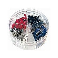
KIT FERRULE INS DIN AWG22-14
Manufacturer
Panduit Corp
Series
Pan-Term®r
Type
Ferrule Kitr
Datasheet
1.KP-FSD1.pdf
(1040 pages)
Specifications of KP-FSD2
Kit Type
Ferrule - Wire End
Values
400 pcs - Assorted Insulated 22 ~ 14 AWG Ferrules
Where Used
To terminate stranded wire for insertion into terminal blocks
Lead Free Status / Rohs Status
Lead free / RoHS Compliant


Management
Identification
Accessories
Connectors
Connectors
& Write-On
Protection
Grounding
Pre-Printed
Cable Ties
Terminals
Permanent
Solutions
Overview
Steel Ties
Lockout/
& Safety
Stainless
Raceway
Abrasion
Labeling
Systems
Markers
Tagout
System
Surface
Wiring
Power
Labels
Index
Cable
Cable
D2.96
Duct
E5.
B1.
B2.
B3.
C1.
C2.
C3.
C4.
D1.
D2.
D3.
E1.
E2.
E3.
E4.
A.
F.
For Use with Flexible and Extra-Flexible Copper Conductors
Type LCCF
• Can be used with flex conductor class: K, M, and Diesel Locomotive
• Long barrel maximizes the number of crimps and provides
• Flared entry prevents bent back strands when inserting fine strand
• Color-coded barrels marked with Panduit die index numbers for
premium wire pull-out strength and electrical performance
conductor into barrel
proper crimp die selection
Order number of pieces required, in multiples of Standard Package Quantity.
‡See pages D3.74, D3.75 for tool and die information.
**Consult cable manufacturer for voltage stress relief instructions with applications greater than 2000 V.
◆NEMA hole sizes and spacing.
Part Number
LCCF8-14A-L
LCCF8-14B-L
LCCF8-38D-L
LCCF6-14A-L
LCCF6-14B-L
LCCF6-38D-L
LCCF4-14A-L
LCCF4-14B-L
LCCF4-38D-L
LCCF2-14A-E
LCCF2-14B-E
LCCF2-56B-E
LCCF2-38D-E
LCCF2-12-E
LCCF1-14A-X
LCCF1-14B-X
LCCF1-56C-X
LCCF1-38D-X
LCCF1-12-X
Flex Conductor, Two-Hole, Long Barrel, Flared NEBS Lug
K and M
#6 AWG
#4 AWG
#2 AWG
#1 AWG
Class
Flex Conductor Size
—
Locomotive
#8 AWG
#6 AWG
#4 AWG
#2 AWG
#1 AWG
Diesel
Stud Hole
Size
(In.)
5/16
5/16
1/4
1/4
3/8
1/4
1/4
3/8
1/4
1/4
3/8
1/4
1/4
3/8
1/2
1/4
1/4
3/8
1/2
ELECTRICAL SOLUTIONS
Stud Hole
Spacing
1.00
1.00
1.00
1.00
1.75
1.00
1.75
(In.)
.63
.75
.63
.75
.63
.75
.63
.75
.75
.63
.75
.88
• Enclosed barrel prevents corrosive material from entering barrel
• Tin-plated to inhibit corrosion
• UL Listed and CSA Certified to 35 KV** and temperature rated to
• Tested by Telcordia – meets NEBS Level 3
• Available with NEMA hole sizes and spacing
T
W
when used in harsh environments
90°C when crimped with Panduit crimping tools and dies
Figure Dimensions (In.)
.48
.48
.60
.48
.48
.62
.55
.55
.62
.70
.70
.70
.70
.75
.76
.76
.76
.76
.80
W
1.22
1.22
1.22
1.23
1.23
1.23
1.36
1.36
1.36
1.36
1.36
1.44
1.44
1.44
1.44
1.44
.76
.76
.76
B
SPACING
HOLE
.07
.07
.05
.08
.08
.06
.09
.09
.08
.11
.11
.11
.11
.09
.12
.12
.12
.12
.12
T
2.22
2.34
2.81
2.71
2.83
3.30
2.75
2.88
3.35
3.00
3.12
3.25
3.57
4.74
3.18
3.31
3.49
3.69
4.86
L
L
Panduit
Brown
Brown
Brown
Brown
Brown
Color
Code
Blue
Blue
Blue
Gray
Gray
Gray
Red
Red
Red
Pink
Pink
Pink
Pink
Pink
B
Die Index
Panduit
No.‡
P21
P21
P21
P24
P24
P24
P29
P29
P29
P33
P33
P33
P33
P33
P42
P42
P42
P42
P42
Prime items appear in BOLD.
FLARED
ENTRY
Wire Strip
Length
1 5/16
1 5/16
1 5/16
1 5/16
1 5/16
1 5/16
1 7/16
1 7/16
1 7/16
1 7/16
1 7/16
13/16
13/16
13/16
1 1/2
1 1/2
1 1/2
1 1/2
1 1/2
(In.)
Pkg.
Std.
Qty.
50
50
50
50
50
50
50
50
50
20
20
20
20
20
10
10
10
10
10