KP-FSD2 Panduit Corp, KP-FSD2 Datasheet - Page 275
KP-FSD2
Manufacturer Part Number
KP-FSD2
Description
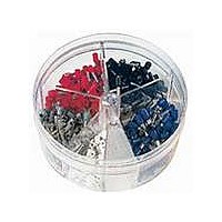
KIT FERRULE INS DIN AWG22-14
Manufacturer
Panduit Corp
Series
Pan-Term®r
Type
Ferrule Kitr
Datasheet
1.KP-FSD1.pdf
(1040 pages)
Specifications of KP-FSD2
Kit Type
Ferrule - Wire End
Values
400 pcs - Assorted Insulated 22 ~ 14 AWG Ferrules
Where Used
To terminate stranded wire for insertion into terminal blocks
Lead Free Status / Rohs Status
Lead free / RoHS Compliant


(22.0)
Panduct
Dimensions are shown for reference only. Contact Panduit customer service at 800-777-3300 for specific dimensional needs.
Panduct
Dimensions are shown for reference only. Contact Panduit customer service at 800-777-3300 for specific dimensional needs.
Panduct
Dimensions are shown for reference only. Contact Panduit customer service at 800-777-3300 for specific dimensional needs.
Part No.
SD2EMI 1.82 (46.1)
SD3EMI 2.88 (73.2)
SD4EMI 3.86 (98.2)
.87
X
(59.6)
TYP.
2.35
(54.0)
2.12
(24.4)
.96
T
.31 (8.0)
(50.8)
TYP.
2.00
TYP.
.10 (2.5)
X
®
®
®
W
5.30 (134.6)
6.25 (158.7)
(50.8)
1.14 (29.0)
TYP.
4.00 (101.6)
2.00
Z
A
PanelMax
2" Duct
PanelMax
PanelMax
.20 (5.0)
Sidewall: SD2EMI shown.
SD3EMI, SD4EMI sidewall feature two
pairs of cable tie slots per section.
.50 (12.7)
.63 (15.9)
(50.8)
2.00
TYP.
C
G
TYP.
H
(20.3)
.80
50° TYP.
™
™
™
Max. Component
Width 2.62 (66.5)
Recommended
A
A
DIN Rail Wiring Duct Dimensions
Noise Shield Dimensions
Corner Wiring Duct Dimensions
(5.0)
TYP.
.20
(7.6)
.30
For technical assistance in the U.S., call 866-405-6654 (outside the U.S., see inside back cover for directory)
Size
CWD3
CWD4
(30.0)
1.18
(79.4)
(72.3)
3.12
TYP.
2.85
View A – A
.10 (2.5)
.20 TYP
[5.0]
(12.7)
All dimension shown in inches (mm).
.50
6.30 (160.0)
7.25 (184.1)
(25.4)
3" Duct
1.00
.50 TYP
[12.7]
E L E C T R I C A L S O LU T I O N S
(126.6)
(150.9)
4.98
5.94
A
.28 (7.0)
D
Bottom view.
(57.2)
(57.2)
2.25
2.25
C
(5.1)
.20
Max. Component
Width 2.67 (67.9)
Recommended
(71.8)
(97.5)
2.83
3.84
.20 TYP
D
[5.0]
Dimensions – Inches (mm)
(104.1)
(79.1)
3.10
4.10
K
(104.8)
G
4.12
(85.1)
(42.7)
TYP.
3.35
1.68
(19.0)
.75
(115.7)
(90.7)
3.57
4.58
H
.10 (2.5)
Bonding clip (for use with
wiring duct).
(100.4)
(124.3)
2.00 [50.8]
7.30 (185.4)
8.25 (209.5)
.50 TYP
4" Duct
3.95
4.89
[12.7]
K
2.00 TYP
(66.6)
2.62
[50.8]
(35.6)
1.40
.16 (4.2)
.28 (7.0)
(2.4)
(2.7)
GAP
.10
.11
T
(111.8)
(135.3)
Max. Component
Width 3.67 (93.3)
4.40
5.33
(5.1)
Recommended
.20
W
(131.0)
(166.0)
5.16
6.54
Z
C1.35
Management
Identification
Accessories
Connectors
Connectors
Grounding
Pre-Printed
& Write-On
Protection
Permanent
Solutions
Cable Ties
Terminals
Lockout/
Overview
Steel Ties
& Safety
Stainless
Raceway
Abrasion
Labeling
Systems
Surface
Markers
Tagout
System
Wiring
Labels
Power
Cable
Cable
Index
Duct
E5.
B1.
B2.
B3.
D1.
D2.
D3.
C1.
C2.
C3.
C4.
E1.
E2.
E3.
E4.
A.
F.