KP-FSD2 Panduit Corp, KP-FSD2 Datasheet - Page 553
KP-FSD2
Manufacturer Part Number
KP-FSD2
Description
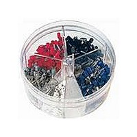
KIT FERRULE INS DIN AWG22-14
Manufacturer
Panduit Corp
Series
Pan-Term®r
Type
Ferrule Kitr
Datasheet
1.KP-FSD1.pdf
(1040 pages)
Specifications of KP-FSD2
Kit Type
Ferrule - Wire End
Values
400 pcs - Assorted Insulated 22 ~ 14 AWG Ferrules
Where Used
To terminate stranded wire for insertion into terminal blocks
Lead Free Status / Rohs Status
Lead free / RoHS Compliant


Crimping Guidelines for Panduit
Splices and Wire Joints (continued)
Insulated and Non-Insulated Butt Splices
A. Locate butt splice in appropriate color-coded crimp die
B. Insert properly stripped wire (based on recommendations
C. Squeeze tool handles firmly to perform the electrical
D. Provide second crimp on the flared portion of the
E. Repeat steps 1 – 4 for opposite end of butt splice.
Non-Insulated Terminals and Disconnects
A. Locate terminal in appropriate wire gauge crimp die
B. Rotate terminal so tongue is level with crimp die.
C. Insert properly stripped wire (based on recommendations
D. Squeeze tool handles firmly to perform the electrical
Insulated and Non-Insulated Parallel Splices
A. Locate parallel splice in appropriate wire gauge crimp die
B. Rotate terminal so tongue is level with crimp die.
C. Insert properly stripped wire (based on recommendations
D. Squeeze tool handles firmly. (See Note 2, page D1.82)
E. An insulation crimp is not required on an insulated
pocket and position crimp halfway between the wire stop
(center of splice) and the end of the insulation crimp area.
(See Note 4, page D1.82)
on package label) into one end of butt splice.
crimp (See Note 2, page D1.82)
insulation housing to close the insulation. Caution: When
using plier type crimping tools, do not squeeze as firmly as
you did for the electrical crimp. (See Note 3, page D1.82)
(See Note 3, page D1.82)
pocket with indenter centered on barrel seam.
on package label) into terminal until a minimum of
1/32'' of wire extends beyond the terminal barrel.
crimp. (See Note 2, page D1.82)
pocket and position tool on the center of the splice.
on package label) into each end of the parallel splice.
parallel splice.
For technical assistance in the U.S., call 866-405-6654 (outside the U.S., see inside back cover for directory)
ELECTRICAL SOLUTIONS
®
Pan-Term
Steps A and B
Steps A and B
Step A
®
Terminals, Disconnects,
Complete Crimp
Complete Crimp
Steps C and D
Step C
Step B
Complete Crimp
Steps D and E
Steps C and D
D1.81
Management
Identification
Accessories
Connectors
Connectors
Grounding
Pre-Printed
& Write-On
Protection
Permanent
Solutions
Cable Ties
Terminals
Lockout/
Overview
Steel Ties
& Safety
Stainless
Raceway
Abrasion
Labeling
Systems
Surface
Markers
Tagout
System
Wiring
Labels
Power
Cable
Cable
Index
Duct
E5.
B1.
B2.
B3.
D1.
D2.
D3.
C1.
C2.
C3.
C4.
E1.
E2.
E3.
E4.
A.
F.