KP-FSD2 Panduit Corp, KP-FSD2 Datasheet - Page 515
KP-FSD2
Manufacturer Part Number
KP-FSD2
Description
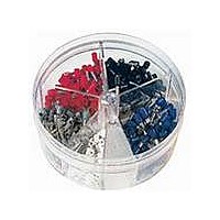
KIT FERRULE INS DIN AWG22-14
Manufacturer
Panduit Corp
Series
Pan-Term®r
Type
Ferrule Kitr
Datasheet
1.KP-FSD1.pdf
(1040 pages)
Specifications of KP-FSD2
Kit Type
Ferrule - Wire End
Values
400 pcs - Assorted Insulated 22 ~ 14 AWG Ferrules
Where Used
To terminate stranded wire for insertion into terminal blocks
Lead Free Status / Rohs Status
Lead free / RoHS Compliant


D = Disconnects
Type DNG-FB
• Disconnect can be inserted and removed from the male tab
• Flared barrel extension integrated into stamping to provide
• Fully insulated design provides protection from electrical shorts
• Internal barrel serrations assure good wire contact and maximum
Part Number System for Pan-Term
without the use of tools for lower installed cost
insulation grip for double crimp requirements
tensile strength
Type
D
L
Supra-Grip
Insulation
N
NF = Nylon,
NFR = Nylon,
NG = Nylon,
NH = Heat Shrink
PF = Premium
R
V
VF = Vinyl
W
NF
= Nylon
= Non-insulated,
= Vinyl
= Non-Insulated
Funnel Entry
Funnel Entry,
Right Angle
Funnel Entry,
Metal
Insulation Grip
Grade Nylon,
Funnel Entry
Right Angle
Funnel Entry
(leave blank)
H
™
Female Disconnect, Nylon Fully Insulated – Funnel Entry
—
*UL Recognized for use with copper alloy tabs.
**Bulk packaging may be available, contact Panduit Customer Service for additional information.
For crimping tool information, see page D1.84.
Part Number
DNG18-187FB-C
DNG18-188FB-C
DNG18-250FB-L
DNG14-187FB-L*
DNG14-188FB-L*
DNG14-250FB-L
For technical assistance in the U.S., call 866-405-6654 (outside the U.S., see inside back cover for directory)
18 = #22 – 18
14 = #16 – 14
10 = #12 – 10
Wire Range
14
®
ELECTRICAL SOLUTIONS
Disconnects
22 – 18
16 – 14
Range
Wire
AWG
AWG
110 = 0.110 x 0.032
111 = 0.110 x 0.020
145 = 0.145 x 0.032
187 = 0.187 x 0.032
188 = 0.187 x 0.020
205 = 0.187/0.205 x 0.032
206 = 0.187/0.205 x 0.020
250 = 0.250 x 0.032
Color
Tab Size
Code
Blue
Red
250
• Internal wire stop assures proper length of insertion into terminal
• Mates with DNF-FIMB family
• UL Flammability UL 94V-2/HB, maximum insulation temperature
• UL and CSA rated up to 600 V per UL 310
barrel, providing a higher-quality connection
221°F (105°C)
0.126
0.126
0.126
0.153
0.153
0.153
Max.
(In.)
Ins.
Figure Dimensions
0.89
0.89
0.93
0.89
0.89
0.93
L
Special Configuration
0.29
0.29
0.35
0.29
0.29
0.35
(In.)
W
A
B
FB
FI
FIB
FIM
FIMB = Fully Insulated, Male
FL
M
M B
P
0.22
0.22
0.22
0.25
0.25
0.25
H
FIB
= Adapter
= Butted Seam
= Metal Insulation
= Fully Insulated,
= Fully Insulated,
= Fully Insulated, Male
= Locking, Metal
= Male
= Butted, Male
= Piggyback
= Female
Grip, Female
Female
Butted Seam, Female
with Oversized Housing
Insulation Grip, Female
(leave blank)
0.187 x 0.032
0.187 x 0.020
0.250 x 0.032
0.187 x 0.032
0.187 x 0.020
0.250 x 0.032
Size
(In.)
Tab
—
Standard Package Size
Recommended
Installation
CT-1015
CT-1015
Tool
L = 50
C = 100
D = 500
M = 1000
M
Qty.**
Pkg.
Std.
100
100
50
50
50
50
1000
1000
Std.
Ctn.
Qty.
250
250
250
250
D1.43
Management
Identification
Accessories
Connectors
Connectors
Grounding
Pre-Printed
& Write-On
Protection
Permanent
Solutions
Cable Ties
Terminals
Lockout/
Overview
Steel Ties
& Safety
Stainless
Raceway
Abrasion
Labeling
Systems
Surface
Markers
Tagout
System
Wiring
Labels
Power
Cable
Cable
Index
Duct
E5.
B1.
B2.
B3.
D1.
D2.
D3.
C1.
C2.
C3.
C4.
E1.
E2.
E3.
E4.
A.
F.