KP-FSD2 Panduit Corp, KP-FSD2 Datasheet - Page 449
KP-FSD2
Manufacturer Part Number
KP-FSD2
Description
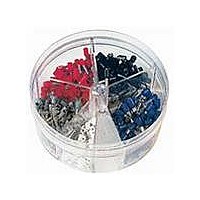
KIT FERRULE INS DIN AWG22-14
Manufacturer
Panduit Corp
Series
Pan-Term®r
Type
Ferrule Kitr
Datasheet
1.KP-FSD1.pdf
(1040 pages)
Specifications of KP-FSD2
Kit Type
Ferrule - Wire End
Values
400 pcs - Assorted Insulated 22 ~ 14 AWG Ferrules
Where Used
To terminate stranded wire for insertion into terminal blocks
Lead Free Status / Rohs Status
Lead free / RoHS Compliant


• Applications include insulating and protecting wires and cables
• Excellent chemical and abrasion resistance
• Use in high temperature or solvent rich environment
• Voltage: 600 V
• Shrink ratio: 2:1
• Flammability: Meets UL 224 VW-1
HSTTVA Heat Shrink 4 Foot and 6 Inch Pieces
• Applications include insulating and protecting wires and cables
• Flexible tubing with an adhesive inner wall which seals and
• Voltage rating: 600 V
• Shrink ratio: 2:1
• Flammability: Outer wall flame retardant
protects components from moisture and corrosion
HSTTK Kynar* Heat Shrink 4 Foot Pieces
4' (1.22m) Pieces
*KYNAR is a registered trademark of Atofina Chemicals, Inc.
Part Number
HSTTVA12-48-Q
HSTTVA19-48-Q
HSTTVA25-48-Q
HSTTVA38-48-Q
HSTTVA50-48-5
HSTTVA75-48-5
HSTTVA100-48-5
HSTTVA150-48-5
Part Number
HSTTK05-48-Q
HSTTK06-48-Q
HSTTK09-48-Q
HSTTK12-48-Q
HSTTK19-48-Q
HSTTK25-48-Q
HSTTK38-48-Q
HSTTK50-48-5
HSTTK75-48-5
HSTTK100-48-5
For technical assistance in the U.S., call 866-405-6654 (outside the U.S., see inside back cover for directory)
ELECTRICAL SOLUTIONS
0.046
0.063
0.093
0.125
0.187
0.250
0.375
0.500
0.750
1.00
In.
Diameter
Nominal
0.125
0.187
0.250
0.375
0.500
0.750
1.00
1.50
In.
Diameter
Nominal
• Mil Spec: AMS-DTL-23053/8
• Temperature range: -67°F to 347°F (-55°C to 175°C)
• For dry locations
• Material: Clear Cross-linked Polyvinylidfene Fluoride (PVDF)
• Mil Spec: AMS-DTL-23053/4 Class 2
• Temperature range: -67°F to 230°F (-55°C to 110°C)
• For damp locations
• Material: Adhesive lined black cross-linked Polyolefin
12.7
19.1
25.4
mm
1.2
1.6
2.4
3.2
4.8
6.4
9.5
12.7
19.1
25.4
38.1
mm
3.2
4.8
6.4
9.5
0.046
0.063
0.093
0.125
0.187
0.250
0.375
0.500
0.750
Expanded I.D.
1.00
In.
0.125
0.187
0.250
0.375
0.500
0.750
1.00
1.50
Expanded
In.
Min.
Min.
I.D.
12.7
19.1
25.4
mm
1.2
1.6
2.4
3.2
4.8
6.4
9.5
12.7
19.1
25.4
38.1
mm
3.2
4.8
6.4
9.5
Max. Recovered
0.023
0.031
0.046
0.062
0.093
0.125
0.187
0.250
0.375
0.500
0.062
0.093
0.125
0.187
0.250
0.375
0.500
0.750
In.
Recovered
In.
Max.
I.D.
I.D.
Table continues on page C3.36
12.7
19.1
12.7
mm
mm
0.6
0.8
1.2
1.6
2.4
3.2
4.8
6.4
9.5
1.6
2.4
3.2
4.8
6.4
9.5
Wall Thickness
Wall Thickness
0.021
0.023
0.029
0.029
0.030
0.035
0.042
0.047
0.010
0.010
0.010
0.010
0.010
0.012
0.012
0.012
0.017
0.019
Recovered
In.
Recovered
In.
Nominal
Nominal
mm
mm
0.5
0.6
0.7
0.7
0.8
0.9
1.1
1.2
0.3
0.3
0.3
0.3
0.3
0.3
0.3
0.3
0.4
0.5
Pkg.
Pkg.
Std.
Qty.
Std.
Qty.
25
25
25
25
25
25
25
25
25
25
25
5
5
5
5
5
5
5
C3.35
Management
Identification
Accessories
Connectors
Connectors
Grounding
Pre-Printed
& Write-On
Protection
Permanent
Solutions
Cable Ties
Terminals
Lockout/
Overview
Steel Ties
& Safety
Stainless
Raceway
Abrasion
Labeling
Systems
Surface
Markers
Tagout
System
Wiring
Labels
Power
Cable
Cable
Index
Duct
E5.
B1.
B2.
B3.
D1.
D2.
D3.
C1.
C2.
C3.
C4.
E1.
E2.
E3.
E4.
A.
F.