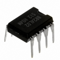
BR24L02-W Rohm Semiconductor, BR24L02-W Datasheet - Page 10

BR24L02-W
Manufacturer Part Number
BR24L02-W
Description
IC EEPROM 2KBIT 400KHZ 8DIP
Manufacturer
Rohm Semiconductor
Datasheet
1.BR24L08F-WE2.pdf
(33 pages)
Specifications of BR24L02-W
Format - Memory
EEPROMs - Serial
Memory Type
EEPROM
Memory Size
2K (256 x 8)
Speed
400kHz
Interface
I²C, 2-Wire Serial
Voltage - Supply
1.8 V ~ 5.5 V
Operating Temperature
-40°C ~ 85°C
Package / Case
8-DIP (0.300", 7.62mm)
Lead Free Status / RoHS Status
Lead free / RoHS Compliant
Available stocks
Company
Part Number
Manufacturer
Quantity
Price
Part Number:
BR24L02-W
Manufacturer:
ROHM/罗姆
Quantity:
20 000
●Read Command
○Read cycle
・In random read cycle, data of designated word address can be read.
・When the command just before current read cycle is random read cycle, current read cycle (each including sequential read
・When ACK signal 'LOW' after D0 is detected, and stop condition is not sent from master (μ-COM) side, the next address
・Read cycle is ended by stop condition where 'H' is input to ACK signal after D0 and SDA signal is started at SCL signal 'H' .
・When 'H' is not input to ACK signal after D0, sequential read gets in, and the next data is output.
・Sequential read is ended by stop condition where 'H' is input to ACK signal after arbitrary D0 and SDA is started at SCL
SDA
LINE
Data of EEPROM is read. In read cycle, there are random read cycle and current read cycle.
Random read cycle is a command to read data by designating address, and is used generally.
Current read cycle is a command to read data of internal address register without designating address, and is used when to
verify just after write cycle. In both the read cycles, sequential read cycle is available, and the next address data can be read
in succession.
S D A
L IN E
SDA
LINE
Therefore, read command cycle cannot be ended. When to end read command cycle, be sure input stop condition to input
'H' to ACK signal after D0, and to start SDA at SCL signal 'H'.
S D A
L IN E
cycle), data of incremented last read address (n)-th address, i.e., data of the (n+1)-th address is output.
data can be read in succession.
signal 'H'.
Note)
Fig.43 Random read cycle (BR24L01A/02/04/08/16-W)
Fig.44 Random read cycle (BR24L32/64 -W)
A
R
Fig.45 Current read cycle
S
T
T
Fig.46 Sequential read cycle (in the case of current read cycle)
R
S
T
A
R
T
S
T
A
T
R
S
T
A
T
1 0
1 0
1 0
1 0
ADDRESS
A D D R E S S
SLAVE
Fig.47 Difference of slave address of each type
1
Note)
ADDRESS
A D D R E S S
Note)
N o te )
S L A V E
SLAVE
1
1
0
S LA V E
1
A2
0
0
N o te)
A1
A 2
A2
0
A0
A 2
A 1
A1
W
R
/
1 0
W
R
T
E
A 0
I
A0
A 1
C
A
K
W
W
A 0
D
W
R
T
E
R
R
E
A
R
/
I
/
*
A
C
K
A
C
K
W
ADDRESS(n)
R
E
A
D
R
* *
/
*1
W A
1st WORD
D7
1
7
A
C
K
WA
12
*1
A D D R E S S (n )
D 7
0
WA
11
DATA(n)
W O R D
*1 *2 *3
A 2
D A TA (n )
A 1
A
C
K
A 0
W A
0
D0
ADDRESS(n)
2nd WORD
A
C
K
C
A
K
D 0
S
A
R
T
T
1 0
A
C
K
A D D R E S S
S
O
P
T
S L A V E
WA
1
0
0
A
C
K
A 2
S
T
A
R
T
A 1
1 0
A 0
ADDRESS
SLAVE
1
W
R
D
R
E
A
A
C
K
/
0
A
C
K
D7
A2 A1
D 7
A0
DATA(n+x)
10/32
R
W
/
R
E
A
D
D A TA (n )
A
C
K
D7
*1 In BR24L16-W, A2 becomes P2.
*2 In BR24L08-W, BR24L16-W, A1 becomes P1.
*3 In BR24L04-W, A0 becomes PS, and in BR24L08-W
DATA(n)
D0
D 0
and BR24L16-W, A0 becomes P0.
A
C
K
A
C
K
S
T
O
P
S
O
P
T
D0
A
C
K
S
T
O
P
*1 As for WA7, BR24L01A-W become Don’t care.
*1 As for WA12, BR24L32-W become Don’t care.
It is necessary to input 'H' to
the last ACK.
It is necessary to input 'H' to
the last ACK.


