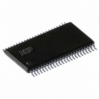
SC28L201A1DGG,112 NXP Semiconductors, SC28L201A1DGG,112 Datasheet - Page 56

SC28L201A1DGG,112
Manufacturer Part Number
SC28L201A1DGG,112
Description
IC UART W/FIFO 48-TSSOP
Manufacturer
NXP Semiconductors
Series
IMPACTr
Datasheet
1.SC28L201A1DGG118.pdf
(110 pages)
Specifications of SC28L201A1DGG,112
Features
False-start Bit Detection
Number Of Channels
2, DUART
Fifo's
256 Byte
Voltage - Supply
3.3V, 5V
With Parallel Port
Yes
With Auto Flow Control
Yes
With False Start Bit Detection
Yes
With Modem Control
Yes
With Cmos
Yes
Mounting Type
Surface Mount
Package / Case
48-TSSOP
Lead Free Status / RoHS Status
Lead free / RoHS Compliant
Other names
568-3293-5
935277824112
SC28L201A1DGG
935277824112
SC28L201A1DGG
Philips Semiconductors
9397 750 13138
Product data sheet
8.2.8 Interrupt Status Register (ISR)
This register provides the status of all potential interrupt sources for a UART channel.
When generating an interrupt arbitration value, the contents of this register are masked by
the interrupt mask register (IMR). If a bit in the ISR is a ‘1’ and the corresponding bit in the
IMR is also a ‘1’, interrupt arbitration for this source will begin. If the corresponding bit in
the IMR is a zero, the state of the bit in the ISR can have no affect on the IRQN output.
Note that the IMR may or may not mask the reading of the ISR as determined by
GCCR[06]. If GCCR[0] is cleared, the reset and power on default, the ISR is read without
modification. If GCCR[0] is set, the read of the ISR gives a value of the ISR ANDed with
the IMR.
Table 25:
Bit
7
6
5
4
3
2
Symbol
ISR - Interrupt Status Register (address 0x25) bit description
Description
I/O port change-of-state. Input change of state.
This bit is set when a change of state occurs at the I/O1 or I/O0 input pins. It is
reset when the CPU reads the Input Port Register, IPR.
Receiver watchdog time-out. Fixed watchdog time-out.
This bit is set when the receiver’s watchdog timer has counted more than 64 bit
times since the last RxFIFO event. RxFIFO events are a read of the RxFIFO or
GRxFIFO, or the load of a received character into the FIFO. The interrupt will
be cleared automatically when the RxFIFO or GRxFIFO is read. The receiver
watchdog timer is included to allow detection of the very last characters of a
received message that may be waiting in the RxFIFO, but are too few in number
to successfully initiate an interrupt. Refer to
timer”
Address recognition event. Address recognition status change.
This bit is set when a change in receiver state has occurred due to an Address
character being received from an external source and matches the reference
address in ARCR. The bit and interrupt is negated by a write to the CR with
command x1 1011, Reset Address Recognition Status.
Xon/Xoff event. Xon/Xoff status change.
This bit is set when an Xon/Xoff character being received from an external
source. The bit is negated by a read of the channel Xon/Xoff Interrupt Status
Register, XISR.
C/T ready. Counter/Timer status.
The C/T has timed-out or the count passed through 0. This bit is cleared by
issuing the ‘stop C/T’ command.
Break change-of-state. Change in channel break status.
This bit, when set, indicates that the receiver has detected the beginning or the
end of a received break. It is reset when the CPU issues a reset break change
interrupt command via the CR.
Rev. 01 — 31 October 2005
for details of how the interrupt system works after a watchdog time-out.
3.3 V, 5 V UART, 3.125 Mbit/s, with 256-byte FIFO
Section 7.4.7.8 “Receiver watchdog
© Koninklijke Philips Electronics N.V. 2005. All rights reserved.
SC28L201
56 of 110


