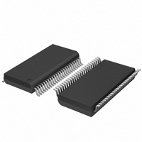
SC28L201A1DGG,118 NXP Semiconductors, SC28L201A1DGG,118 Datasheet - Page 12

SC28L201A1DGG,118
Manufacturer Part Number
SC28L201A1DGG,118
Description
IC UART W/FIFO 48-TSSOP
Manufacturer
NXP Semiconductors
Series
IMPACTr
Datasheet
1.SC28L201A1DGG118.pdf
(110 pages)
Specifications of SC28L201A1DGG,118
Features
False-start Bit Detection
Number Of Channels
2, DUART
Fifo's
256 Byte
Voltage - Supply
3.3V, 5V
With Parallel Port
Yes
With Auto Flow Control
Yes
With False Start Bit Detection
Yes
With Modem Control
Yes
With Cmos
Yes
Mounting Type
Surface Mount
Package / Case
48-TSSOP
Lead Free Status / RoHS Status
Lead free / RoHS Compliant
Other names
935277824118
SC28L201A1DGG-T
SC28L201A1DGG-T
SC28L201A1DGG-T
SC28L201A1DGG-T
Philips Semiconductors
9397 750 13138
Product data sheet
6.1.10 Flow control
6.1.11 Test modes
6.1.9 Character and address recognition
The content of the current interrupt register also drives the Global Registers of the
interrupt system. These registers are indirect addresses (pointers) to the interrupt source
requesting service.
Programming of Bid Control Registers allows the interrupt level of any source to be varied
at any time over a range of 256 levels.
The character recognition system is designed first and foremost as a general-purpose
system that can give an interrupt on the reception or transmission on any of three
user-defined characters. A subblock of this system is the special function related to
Xon/Xoff flow control and the ‘9-bit mode’.
The recognition block stores up to three characters. The recognition is done on a byte
boundary and sets status and interrupt when recognition events occur. Three modes of
automatic operation are provided for the in-band flow control (Xon/Xoff) and three modes
of automatic operation are provided for address recognition (9-bit or multi-drop mode).
Both in-band flow control and address recognition may also be completely under the
control of the host processor.
A subset of the recognition system is Xon/Xoff character recognition and the recognition
of the multi-drop address character. If Xon/Xoff or multi-drop function is enabled the
recognition system passes the information about the recognition event to the appropriate
receiver or transmitter state machine for execution. In any case, the information about a
recognition event is available to the interrupt system and to the control processor.
Another subset of the character recognition is recognition of the address character itself
(the character value) used in the multi-drop or 9-bit mode. Here also four levels of
automatic operation are available. The most interrupt efficient is the ‘auto-wake/auto-doze’
level which relieves the processor of any tasks.
Flow control is implemented in either the traditional RTS/CTS protocol or in the inbound
Xon/Xoff method. Both may be controlled by fully/partially automatic methods or by
interrupt generation.
The three test modes, auto echo, local loopback, and remote loopback, are provided to
verify UART function and processor interface integrity at the system level. The local
loopback, however, is directed a little more toward the control processor to the UART
interface. Through it the software developer may verify all of the interrupt, flow control; the
hardware designer may verify all of the timing and pin connections. This information is
obtained without any recourse to external test equipment, logic analyzers or terminals.
The auto echo and remote loopback are meant to test the communication channel after it
is established that the processor to UART interface is well established.
Rev. 01 — 31 October 2005
3.3 V, 5 V UART, 3.125 Mbit/s, with 256-byte FIFO
© Koninklijke Philips Electronics N.V. 2005. All rights reserved.
SC28L201
12 of 110


