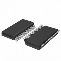
SC28L201A1DGG,118 NXP Semiconductors, SC28L201A1DGG,118 Datasheet - Page 10

SC28L201A1DGG,118
Manufacturer Part Number
SC28L201A1DGG,118
Description
IC UART W/FIFO 48-TSSOP
Manufacturer
NXP Semiconductors
Series
IMPACTr
Datasheet
1.SC28L201A1DGG118.pdf
(110 pages)
Specifications of SC28L201A1DGG,118
Features
False-start Bit Detection
Number Of Channels
2, DUART
Fifo's
256 Byte
Voltage - Supply
3.3V, 5V
With Parallel Port
Yes
With Auto Flow Control
Yes
With False Start Bit Detection
Yes
With Modem Control
Yes
With Cmos
Yes
Mounting Type
Surface Mount
Package / Case
48-TSSOP
Lead Free Status / RoHS Status
Lead free / RoHS Compliant
Other names
935277824118
SC28L201A1DGG-T
SC28L201A1DGG-T
SC28L201A1DGG-T
SC28L201A1DGG-T
Philips Semiconductors
9397 750 13138
Product data sheet
6.1.2.1 Crystal oscillator
6.1.2.2 Fixed rate Baud Rate Generator (BRG)
6.1.2.3 Counter/Timer
6.1.2.4 Programmable BRG (PBRG)
6.1.2 Timing circuits
6.1.3 I/O ports
The crystal oscillator is the main timing element for the SC28L201. It is nominally set at
14.7456 MHz. Operation with a crystal as a frequency standard is specified from 7 MHz to
16.2 MHz. The use of an external clock allows all frequencies to 50 MHz. Clock prescalers
are provided to match various available system clocks to those needed for baud rate
generation.
Remark: If an external clock is used, X2 should not drive more than 2 CMOS or 2 TTL
equivalents.
The BRG is driven by the X1/SCLK input through a programmable prescale divider. It
generates all of the 27 ‘fixed’ internal baud rates. This baud rate generator is designed to
generate the industry standard baud rates from a 14.7456 MHz crystal or clock frequency.
X1/SCLK frequencies different from 14.7456 MHz will cause the ‘fixed’ baud rates to
change by exactly the ratio of 14.7456 to the different frequency.
The two Counter/Timers are programmable 16-bit ‘down’ counters. It provides
miscellaneous baud rates, timing periods and acts as an extra watchdog timer for the
receivers. It has 8 programmable clock sources derived from internal and external signals.
It may also act as a character counter for the receiver. Interrupts from the Counter/Timer
are generated as it passes through zero.
This is another 16-bit programmable counter to generate only baud rates or
miscellaneous clock frequencies. Its output is available to the receiver and transmitter and
may be delivered to I/O ports. It has 8 programmable clock sources derived from internal
and external signals.
The SC28L201 is provided with 14 I/O ports. These ports are true input and/or output
structures and are equipped with a change of state detector. The input circuit of these pins
is always active. Under program control the ports my display internal signals or static logic
levels. The functions represented by the I/O ports include hardware flow control. Modem
signals, signals for interrupt conditions or various internal clocks and timing intervals.
Each I/O pin has a change of state detector attached to it. These are used to alert the
processor to slow or infrequent signals, modem signals, alarm, power alerts, and so on.
For the signals to qualify for Change-Of-State (COS) detection, the signal must be stable
for a time of 25 s to 50 s (one to two cycles of the 38.4 kBd clock).
The input logic of these pins is always active, even when defined as an output. Therefore,
it would be possible for the chip to count the number of times the RTS or CTS signal
occurred, thus giving an indication of interrupt latency.
Rev. 01 — 31 October 2005
3.3 V, 5 V UART, 3.125 Mbit/s, with 256-byte FIFO
© Koninklijke Philips Electronics N.V. 2005. All rights reserved.
SC28L201
10 of 110


