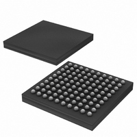
DS3170N+ Maxim Integrated Products, DS3170N+ Datasheet - Page 152

DS3170N+
Manufacturer Part Number
DS3170N+
Description
IC TXRX DS3/E3 100-CSBGA
Manufacturer
Maxim Integrated Products
Datasheet
1.DS3170.pdf
(230 pages)
Specifications of DS3170N+
Function
Single-Chip Transceiver
Interface
DS3, E3
Number Of Circuits
1
Voltage - Supply
3.135 V ~ 3.465 V
Current - Supply
120mA
Operating Temperature
-40°C ~ 85°C
Mounting Type
Surface Mount
Package / Case
100-LBGA
Includes
DS3 Framers, E3 Framers, HDLC Controller, On-Chip BERTs
Lead Free Status / RoHS Status
Lead free / RoHS Compliant
Power (watts)
-
- Current page: 152 of 230
- Download datasheet (3Mb)
12.5.2 Receive Side Line Encoder/Decoder Register Map
The receive side utilizes six registers.
Table 12-15. Receive Side B3ZS/HDB3 Line Encoder/Decoder Register Map
12.5.2.1 Register Bit Descriptions
Register Name:
Register Description:
Register Address:
Bit #
Name
Default
Bit #
Name
Default
Bit 2: E3 Code Violation Enable (E3CVE) – When 0, the bipolar violation count will be a count of bipolar
violations. When 1, the bipolar violation count will be a count of E3 line coding violations. Note: E3 line coding
violations are defined as consecutive bipolar violations of the same polarity in ITU O.161. This bit is ignored in
B3ZS mode.
Bit 2: Receive BPV Error Detection Zero Suppression Code Format (REZSF) – When 0, BPV error detection
detects a B3ZS signature if a zero is followed by a bipolar violation (BPV), and an HDB3 signature if two zeros are
followed by a BPV. When 1, BPV error detection detects a B3ZS signature if a zero is followed by a BPV that has
the opposite polarity of the BPV in the previous B3ZS signature, and an HDB3 signature if two zeros are followed
by a BPV that has the opposite polarity of the BPV in the previous HDB3 signature. Note: Immediately after a reset,
this bit is ignored. The first B3ZS signature is defined as a zero followed by a BPV, and the first HDB3 signature is
defined as two zeros followed by a BPV. All subsequent B3ZS/HDB3 signatures will be determined by the setting of
this bit.
Note: The default setting (REZSF = 0) conforms to ITU O.162. The default setting may falsely decode actual BPVs
that are not codewords. It is recommended that REZSF be set to one for most applications. This setting is more
robust to accurately detect codewords.
Bit 1: Receive Zero Suppression Decoding Zero Suppression Code Format (RDZSF) – When 0, zero
suppression decoding detects a B3ZS signature if a zero is followed by a bipolar violation (BPV), and an HDB3
signature if two zeros are followed by a BPV. When 1, zero suppression decoding detects a B3ZS signature if a
zero is followed by a BPV that has the opposite polarity of the BPV in the previous B3ZS signature, and an HDB3
signature if two zeros are followed by a BPV that has the opposite polarity of the BPV in the previous HDB3
signature. Note: Immediately after a reset (DRST or RST low), this bit is ignored. The first B3ZS signature is defined
as a zero followed by a BPV, and the first HDB3 signature is defined as two zeros followed by a BPV. All
subsequent B3ZS/HDB3 signatures will be determined by the setting of this bit.
Address
09Ah
09Ch
09Eh
090h
092h
094h
096h
098h
15
LINE.RCR
LINE.RSR
LINE.RSRL
LINE.RSRIE
LINE.RBPVCR
LINE.REXZCR
--
--
0
7
0
Register
--
--
14
--
--
0
6
0
LINE.RCR
Line Receive Control Register
(0.2.4.6)90h
Line Receive Control Register
Unused
Line Receive Status Register
Line Receive Status Register Latched
Line Receive Status Register Interrupt Enable
Unused
Line Receive Bipolar Violation Count Register
Line Receive Excessive Zero Count Register
Register Description
13
--
--
0
5
0
152 of 230
12
--
--
0
4
0
E3CVE
11
--
0
3
0
DS3170 DS3/E3 Single-Chip Transceiver
REZSF
10
--
0
2
0
RDZSF
--
9
0
1
0
RZSD
--
8
0
0
0
Related parts for DS3170N+
Image
Part Number
Description
Manufacturer
Datasheet
Request
R

Part Number:
Description:
IC TXRX DS3/E3 100-CSBGA
Manufacturer:
Maxim Integrated Products
Datasheet:

Part Number:
Description:
Network Controller & Processor ICs DS3-E3 Single-Chip T ransceiver T3-E3 Fra
Manufacturer:
Maxim Integrated Products
Datasheet:

Part Number:
Description:
MAX7528KCWPMaxim Integrated Products [CMOS Dual 8-Bit Buffered Multiplying DACs]
Manufacturer:
Maxim Integrated Products
Datasheet:

Part Number:
Description:
Single +5V, fully integrated, 1.25Gbps laser diode driver.
Manufacturer:
Maxim Integrated Products
Datasheet:

Part Number:
Description:
Single +5V, fully integrated, 155Mbps laser diode driver.
Manufacturer:
Maxim Integrated Products
Datasheet:

Part Number:
Description:
VRD11/VRD10, K8 Rev F 2/3/4-Phase PWM Controllers with Integrated Dual MOSFET Drivers
Manufacturer:
Maxim Integrated Products
Datasheet:

Part Number:
Description:
Highly Integrated Level 2 SMBus Battery Chargers
Manufacturer:
Maxim Integrated Products
Datasheet:

Part Number:
Description:
Current Monitor and Accumulator with Integrated Sense Resistor; ; Temperature Range: -40°C to +85°C
Manufacturer:
Maxim Integrated Products

Part Number:
Description:
TSSOP 14/A°/RS-485 Transceivers with Integrated 100O/120O Termination Resis
Manufacturer:
Maxim Integrated Products

Part Number:
Description:
TSSOP 14/A°/RS-485 Transceivers with Integrated 100O/120O Termination Resis
Manufacturer:
Maxim Integrated Products

Part Number:
Description:
QFN 16/A°/AC-DC and DC-DC Peak-Current-Mode Converters with Integrated Step
Manufacturer:
Maxim Integrated Products

Part Number:
Description:
TDFN/A/65V, 1A, 600KHZ, SYNCHRONOUS STEP-DOWN REGULATOR WITH INTEGRATED SWI
Manufacturer:
Maxim Integrated Products

Part Number:
Description:
Integrated Temperature Controller f
Manufacturer:
Maxim Integrated Products

Part Number:
Description:
SOT23-6/I°/45MHz to 650MHz, Integrated IF VCOs with Differential Output
Manufacturer:
Maxim Integrated Products

Part Number:
Description:
SOT23-6/I°/45MHz to 650MHz, Integrated IF VCOs with Differential Output
Manufacturer:
Maxim Integrated Products


