MC68EC020AA25 Freescale Semiconductor, MC68EC020AA25 Datasheet - Page 37
MC68EC020AA25
Manufacturer Part Number
MC68EC020AA25
Description
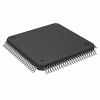
IC MPU 32BIT 25MHZ 100-QFP
Manufacturer
Freescale Semiconductor
Datasheet
1.MC68EC020AA16.pdf
(306 pages)
Specifications of MC68EC020AA25
Processor Type
M680x0 32-Bit
Speed
25MHz
Voltage
5V
Mounting Type
Surface Mount
Package / Case
100-QFP
Family Name
M68000
Device Core
ColdFire
Device Core Size
32b
Frequency (max)
25MHz
Instruction Set Architecture
RISC
Supply Voltage 1 (typ)
5V
Operating Supply Voltage (max)
5.25V
Operating Supply Voltage (min)
4.75V
Operating Temp Range
0C to 70C
Operating Temperature Classification
Commercial
Mounting
Surface Mount
Pin Count
100
Package Type
PQFP
Lead Free Status / RoHS Status
Lead free / RoHS Compliant
Features
-
Lead Free Status / Rohs Status
RoHS Compliant part
Electrostatic Device
Available stocks
Company
Part Number
Manufacturer
Quantity
Price
Company:

Part Number:
MC68EC020AA25
Manufacturer:
Freescale Semiconductor
Quantity:
10 000
Company:
Part Number:
MC68EC020AA25R
Manufacturer:
Freescale Semiconductor
Quantity:
10 000


3.1 SIGNAL INDEX
The input and output signals for the MC68020/EC020 are listed in Table 3-1. Both the
names and mnemonics are shown along with brief signal descriptions. Signals that are
implemented in the MC68020, but not in the MC68EC020, have an asterisk (*) preceding
the signal name in Table 3-1. Also, note that the address bus is 32 bits wide for the
MC68020 and 24 bits wide for the MC68EC020. For more detail on each signal, refer to
the paragraph in this section named for the signal and the reference in that paragraph to a
description of the related operations.
Timing specifications for the signals listed in Table 3-1 can be found in Section 10
Electrical Characteristics.
3.2 FUNCTION CODE SIGNALS (FC2–FC0)
These three-state outputs identify the address space of the current bus cycle. Table 2-1
shows the relationships of the function code signals to the privilege levels and the address
spaces. Refer to Section 2 Processing States for more information.
3.3 ADDRESS BUS (A31–A0, MC68020)(A23–A0, MC68EC020)
These three-state outputs provide the address for the current bus cycle, except in the
CPU address space. Refer to Section 2 Processing States for more information on the
CPU address space. A31 is the most significant address signal for the MC68020; A23 is
the most significant address signal for the MC68EC020. The upper eight bits (A31–A24)
are used internally by the MC68EC020 to access the internal instruction cache address
tag. Refer to Section 5 Bus Operation for information on the address bus and its
relationship to bus operation.
3.4 DATA BUS (D31–D0)
These three-state bidirectional signals provide the general-purpose data path between the
MC68020/EC020 and all other devices. The data bus can transfer 8, 16, 24, or 32 bits of
data per bus cycle. D31 is the most significant bit of the data bus. Refer to Section 5 Bus
Operation for more information on the data bus and its relationship to bus operation.
3.5 TRANSFER SIZE SIGNALS (SIZ1, SIZ0)
These three-state outputs indicate the number of bytes remaining to be transferred for the
current bus cycle. Signals A1, A0, DSACK1, DSACK0, SIZ1, and SIZ0 define the number
of bits transferred on the data bus. Refer to Section 5 Bus Operation for more
information on SIZ1 and SIZ0 and their use in dynamic bus sizing.
3- 2
M68020 USER’S MANUAL
MOTOROLA
Related parts for MC68EC020AA25
Image
Part Number
Description
Manufacturer
Datasheet
Request
R

Part Number:
Description:
Manufacturer:
Freescale Semiconductor, Inc
Datasheet:
Part Number:
Description:
Manufacturer:
Freescale Semiconductor, Inc
Datasheet:
Part Number:
Description:
Manufacturer:
Freescale Semiconductor, Inc
Datasheet:
Part Number:
Description:
Manufacturer:
Freescale Semiconductor, Inc
Datasheet:
Part Number:
Description:
Manufacturer:
Freescale Semiconductor, Inc
Datasheet:
Part Number:
Description:
Manufacturer:
Freescale Semiconductor, Inc
Datasheet:
Part Number:
Description:
Manufacturer:
Freescale Semiconductor, Inc
Datasheet:
Part Number:
Description:
Manufacturer:
Freescale Semiconductor, Inc
Datasheet:
Part Number:
Description:
Manufacturer:
Freescale Semiconductor, Inc
Datasheet:
Part Number:
Description:
Manufacturer:
Freescale Semiconductor, Inc
Datasheet:
Part Number:
Description:
Manufacturer:
Freescale Semiconductor, Inc
Datasheet:
Part Number:
Description:
Manufacturer:
Freescale Semiconductor, Inc
Datasheet:
Part Number:
Description:
Manufacturer:
Freescale Semiconductor, Inc
Datasheet:
Part Number:
Description:
Manufacturer:
Freescale Semiconductor, Inc
Datasheet:
Part Number:
Description:
Manufacturer:
Freescale Semiconductor, Inc
Datasheet: