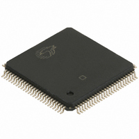
CY7C67300-100AXI Cypress Semiconductor Corp, CY7C67300-100AXI Datasheet - Page 12

CY7C67300-100AXI
Manufacturer Part Number
CY7C67300-100AXI
Description
IC USB HOST/PERIPH CNTRL 100LQFP
Manufacturer
Cypress Semiconductor Corp
Series
EZ-Host™r
Type
Host Programmable Embedded USBr
Datasheet
1.CY7C67300-100AXI.pdf
(99 pages)
Specifications of CY7C67300-100AXI
Package / Case
100-LQFP
Applications
USB Host/Peripheral Controller
Core Processor
CY16
Program Memory Type
ROM (8 kB)
Controller Series
CY7C673xx
Ram Size
16K x 8
Interface
SPI Serial, USB, HPI
Number Of I /o
32
Voltage - Supply
3 V ~ 3.6 V
Operating Temperature
-40°C ~ 85°C
Mounting Type
Surface Mount
Maximum Operating Temperature
+ 85 C
Minimum Operating Temperature
- 40 C
Mounting Style
SMD/SMT
Operating Temperature Range
- 40 C to + 85 C
Supply Current
80 mA
Operating Supply Voltage
3.3 V
Lead Free Status / RoHS Status
Lead free / RoHS Compliant
For Use With
CY4640 - KIT MASS STORAGE REF DESIGNCY3663 - KIT DEV EZ-OTG/EZ-HOST
Lead Free Status / Rohs Status
Lead free / RoHS Compliant
Other names
428-1865
CY7C67300-100AXI
CY7C67300-100AXI
Available stocks
Company
Part Number
Manufacturer
Quantity
Price
Company:
Part Number:
CY7C67300-100AXI
Manufacturer:
ATMEL
Quantity:
210
Company:
Part Number:
CY7C67300-100AXI
Manufacturer:
CYPRESS
Quantity:
246
Company:
Part Number:
CY7C67300-100AXI
Manufacturer:
Cypress Semiconductor Corp
Quantity:
10 000
Part Number:
CY7C67300-100AXI
Manufacturer:
CYPRESS
Quantity:
20 000
Company:
Part Number:
CY7C67300-100AXIT
Manufacturer:
Cypress Semiconductor Corp
Quantity:
10 000
Boot Configuration Interface
EZ-Host can boot into any one of four modes. The mode it boots
into is determined by the TTL voltage level of GPIO[31:30] at the
time nRESET is deasserted.
pin combinations possible. After a reset pin event occurs, the
BIOS bootup procedure executes for up to 3 ms. GPIO[31:30]
are sampled by the BIOS during bootup only. After bootup these
pins are available to the application as GPIOs.
Table 19. Boot Configuration Interface
Ensure that GPIO[31:30] is pulled high or low as needed using
resistors tied to V
ohms and 15K ohms. Do not tie GPIO[31:30] directly to V
GND. Note that in standalone mode, the pull ups on those two
pins are used for the serial I2C EEPROM (if implemented). Make
sure that the resistors used for these pull ups conform to the
serial EEPROM manufacturer's requirements.
If any mode other then standalone is chosen, EZ-Host is in
coprocessor mode. The device powers up with the appropriate
communication interface enabled according to its boot pins and
waits idle until a coprocessor communicates with it. See the
BIOS documentation for greater detail of the boot process.
Document #: 38-08015 Rev. *J
GPIO31
(Pin 39)
0
0
1
1
GPIO30
(Pin 40)
0
1
0
1
CC
or GND with resistor values between 5K
Host Port Interface (HPI)
High-Speed Serial (HSS)
Serial Peripheral Interface (SPI,
slave mode)
I
2
C EEPROM (Standalone Mode)
Table 19
Boot Mode
shows the different boot
CC
or
Operational Modes
The operational modes are discussed in the following sections.
Coprocessor Mode
EZ-Host can act as a coprocessor to an external host processor.
In this mode, an external host processor drives EZ-Host and is
the main processor rather then EZ-Host’s own 16-bit internal
CPU. An external host processor may interface to EZ-Host
through one of the following three interfaces in coprocessor
mode:
■
■
■
At bootup GPIO[31:30] determine which of these three interfaces
are used for coprocessor mode. See
Bootloading begins from the selected interface after POR + 3 ms
of BIOS bootup.
Standalone Mode
In standalone mode, there is no external processor connected to
EZ-Host. Instead, EZ-Host’s own internal 16-bit CPU is the main
processor and firmware is typically downloaded from an
EEPROM. Optionally, firmware may also be downloaded via
USB. See
After booting into standalone mode (GPIO[31:30] = ‘11’), the
following pins are affected:
■
■
■
■
■
HPI mode, a 16 bit parallel interface with up to 16 MB transfer
rate
HSS mode, a serial interface with up to 2M baud transfer rate
SPI mode, a serial interface with up to 2 Mb/s transfer rate
GPIO[31:30] are configured as output pins to examine the
EEPROM contents
GPIO[28:27] are enabled for debug UART mode
GPIO[29] is configured for as OTGID for OTG applications on
PORT1A
❐
❐
Ports 1B, 2A, and 2B default as USB peripheral ports
All other pins remain INPUT pins.
If OTGID is logic 1 then PORT1A (OTG) is configured as a
USB peripheral
If OTGID is logic 0 then PORT1A (OTG) is configured as a
USB host
Table 19
for booting into standalone mode.
Table 19
CY7C67300
Page 12 of 99
for details.
[+] Feedback


