8080-1G7 TE Connectivity, 8080-1G7 Datasheet - Page 48
8080-1G7
Manufacturer Part Number
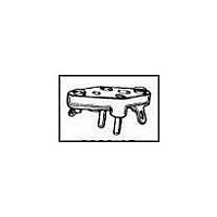
8080-1G7
Description
TRANSISTOR SOCKET, 3POS, THROUGH HOLE
Manufacturer
TE Connectivity
Datasheet
1.8080-1G7.pdf
(80 pages)
Specifications of 8080-1G7
Connector Type
TO-3 Socket
No. Of Contacts
3
Pitch Spacing
5.46mm
Contact Termination
Solder
Contact Material
Beryllium Copper
Contact Plating
Gold
Socket Mounting
PC Board
Rohs Compliant
No
Product Type
Socket
Terminal Configuration
Contact
Product Series
8080-1G Series
Package
TO-3
Number Of Solder Lugs
2
Terminal Plating
Gold
Terminal Style
Solder
Number Of Terminals
3
Socket Type
Transistor
Terminal Material
Beryllium Copper
Insulator Material
Phenolic
Lead Size Accepted (mm [in])
1.02 [0.040]
Rohs/elv Compliance
Not ELV/RoHS compliant
Lead Free Solder Processes
Wave solder capable to 240°C, Wave solder capable to 260°C, Wave solder capable to 265°C
Operating Temperature (°c)
-55 – +125


5048
FEATURES:
The 600 Series is a high quality machined pin molded adaptor which is
used to assemble hybrid and special network circuits. The .018" (0,46)
diameter precision pin allows the adaptor to be plugged into socket or
wire wrappable panels repeatedly.
• Precision machined pins
• Used for interposing discrete components
• Terminals are the same dimension as IC board patterns
• Option of round, solder pocket or slotted pin styles
• Thermoplastic polyester insulators
• Large variety of styles:
MATERIAL SPECIFICATIONS:
Insulator ..................Thermoplastic polyester, UL rated 94V-0
Pins ………………Phospher bronze, gold or tin/lead plated
600 Series
Note: Before ordering, see Cross Reference in Section 15 for
equivalent Tyco Electronics Part Number.
Products for Industrial &
Commercial Applications
8, 14, 16, 20 pins - .300" (7,62) between rows
22 pins - .400"(10,16) between rows
14, 16, 24, 28, 32, 36, and 40 pins - .600" (15,24) between rows
14 & 16 pins - .800" (20,32) between rows
Dimensions are shown for
reference purposes only.
Adapters
Plug Adapter Assemblies
Dimensions are in inches and
millimeters unless otherwise
specified. Values in brackets
are metric equivalents.
PERFORMANCE SPECIFICATIONS:
MECHANICAL
Vibration ..........................Tested to a frequency range of 10 to 2,000 Hz
Mechanical Shock............Will meet the requirements of MIL-STD-202,
ELECTRICAL
Current Rating..................5 Amps when tested with a 30-gauge wire
Capacitance ......................At a test frequency of 1 KHz, adjacent and/or
Dielectric Withstanding ..
Insulation Resistance ......1 x 10 12 Ohms, tested to MIL-STD 202,
ENVIRONMENTAL
Thermal Shock ................No visual damage when tested in accordance
Operating
Salt Spray ........................No visual evidence of corrosion on Gold
Voltage ..........................1,000 VRMS @ 30 inches mercury, .500 VRMS
Temperatures..................-65°C to +125°C
Specifications subject to
change.
614-CG1
Adjacent terminal:
Opposite Terminal:
AG and CG solder tail.........................36pF
BG (solder pocket) ..............................42pF
AG and CG solder tail.........................025pF
BG (solder pocket) ..............................034pF
-65°C to +150°C
Method 101 Test condition B for 48 hours
and returned to 10Hz in three perpendicular
planes at a double amplitude of .06" (1,52) or
20 G's, whichever was less per MIL-STD-
202, Method 204
Method 213 when subjected to a shock test
at 150 G's acceleration
attached. Terminal will have a maximum
30°C temperature rise above ambient
terminal all at guard potential
when tested @ 0.9 inches mercury, tested per
MIL-STD-202, Method 301
Method 302, tested @ 500 Volts
with MIL-STD-202, Method 107, test
condition F for 5 consecutive cycles of
terminals when tested per MIL-STD-202,
and a 5% salt solution
Technical Support Center
1-800-522-6752
www.tycoelectronics.com
Catalog 1307612
Revised 7-01
Related parts for 8080-1G7
Image
Part Number
Description
Manufacturer
Datasheet
Request
R

Part Number:
Description:
Manufacturer:
TE Connectivity
Datasheet:


Part Number:
Description:
Manufacturer:
TE Connectivity
Datasheet:


Part Number:
Description:
Manufacturer:
TE Connectivity
Datasheet:

Part Number:
Description:
Manufacturer:
TE Connectivity
Datasheet:

Part Number:
Description:
Manufacturer:
TE Connectivity
Datasheet:


Part Number:
Description:
Manufacturer:
TE Connectivity
Datasheet:

Part Number:
Description:
Manufacturer:
TE Connectivity
Datasheet: