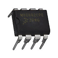
MC68HC908QT2CPE Freescale, MC68HC908QT2CPE Datasheet - Page 71

MC68HC908QT2CPE
Manufacturer Part Number
MC68HC908QT2CPE
Description
Manufacturer
Freescale
Datasheet
1.MC68HC908QT2CPE.pdf
(184 pages)
Specifications of MC68HC908QT2CPE
Cpu Family
HC08
Device Core Size
8b
Frequency (max)
8MHz
Total Internal Ram Size
128Byte
# I/os (max)
6
Number Of Timers - General Purpose
2
Operating Supply Voltage (typ)
3.3/5V
Operating Supply Voltage (max)
5.5V
Operating Supply Voltage (min)
2.7V
On-chip Adc
4-chx8-bit
Instruction Set Architecture
CISC
Operating Temp Range
-40C to 85C
Operating Temperature Classification
Industrial
Mounting
Through Hole
Pin Count
8
Package Type
PDIP
Program Memory Type
Flash
Program Memory Size
1.5KB
Lead Free Status / RoHS Status
Compliant
- Current page: 71 of 184
- Download datasheet (2Mb)
7.8 Opcode Map
See
Freescale Semiconductor
SWI
TAP
TAX
TPA
TST opr
TSTA
TSTX
TST opr,X
TST ,X
TST opr,SP
TSX
TXA
TXS
WAIT
A
C
CCR
dd
dd rr
DD
DIR
DIX+
ee ff
EXT
ff
H
H
hh ll
I
ii
IMD
IMM
INH
IX
IX+
IX+D
IX1
IX1+
IX2
M
N
Source
Form
Table
Accumulator
Carry/borrow bit
Condition code register
Direct address of operand
Direct address of operand and relative offset of branch instruction
Direct to direct addressing mode
Direct addressing mode
Direct to indexed with post increment addressing mode
High and low bytes of offset in indexed, 16-bit offset addressing
Extended addressing mode
Offset byte in indexed, 8-bit offset addressing
Half-carry bit
Index register high byte
High and low bytes of operand address in extended addressing
Interrupt mask
Immediate operand byte
Immediate source to direct destination addressing mode
Immediate addressing mode
Inherent addressing mode
Indexed, no offset addressing mode
Indexed, no offset, post increment addressing mode
Indexed with post increment to direct addressing mode
Indexed, 8-bit offset addressing mode
Indexed, 8-bit offset, post increment addressing mode
Indexed, 16-bit offset addressing mode
Memory location
Negative bit
7-2.
Software Interrupt
Transfer A to CCR
Transfer A to X
Transfer CCR to A
Test for Negative or Zero
Transfer SP to H:X
Transfer X to A
Transfer H:X to SP
Enable Interrupts; Wait for Interrupt
Operation
Table 7-1. Instruction Set Summary (Sheet 6 of 6)
MC68HC908QY/QT Family Data Sheet, Rev. 6
(A) – $00 or (X) – $00 or (M) – $00
PCH ← Interrupt Vector High Byte
PCL ← Interrupt Vector Low Byte
I bit ← 0; Inhibit CPU clocking
PC ← (PC) + 1; Push (PCL)
SP ← (SP) – 1; Push (PCH)
SP ← (SP) – 1; Push (CCR)
SP ← (SP) – 1; Push (X)
SP ← (SP) – 1; Push (A)
SP ← (SP) – 1; I ← 1
(SP) ← (H:X) – 1
H:X ← (SP) + 1
until interrupted
Description
CCR ← (A)
A ← (CCR)
X ← (A)
A ← (X)
n
opr
PC
PCH Program counter high byte
PCL Program counter low byte
REL Relative addressing mode
rel
rr
SP1 Stack pointer, 8-bit offset addressing mode
SP2 Stack pointer 16-bit offset addressing mode
SP
U
V
X
Z
&
|
⊕
( )
–( )
#
«
←
?
:
—
Any bit
Relative program counter offset byte
Undefined
Overflow bit
Index register low byte
Zero bit
Logical AND
Negation (two’s complement)
Operand (one or two bytes)
Program counter
Relative program counter offset byte
Stack pointer
Logical OR
Logical EXCLUSIVE OR
Contents of
Immediate value
Sign extend
Loaded with
If
Concatenated with
Set or cleared
Not affected
V H I N Z C
– – 1 – – – INH
– – – – – – INH
– – – – – – INH
0 – –
– – – – – – INH
– – – – – – INH
– – – – – – INH
– – 0 – – – INH
on CCR
Effect
–
INH
DIR
INH
INH
IX1
IX
SP1
9E6D
3D
4D
5D
6D
7D
83
84
97
85
95
9F
94
8F
Opcode Map
dd
ff
ff
71
9
2
1
1
3
1
1
3
2
4
2
1
2
1
Related parts for MC68HC908QT2CPE
Image
Part Number
Description
Manufacturer
Datasheet
Request
R

Part Number:
Description:
TOWER ELEVATOR BOARDS HARDWARE
Manufacturer:
Freescale Semiconductor
Datasheet:

Part Number:
Description:
TOWER SERIAL I/O HARDWARE
Manufacturer:
Freescale Semiconductor
Datasheet:

Part Number:
Description:
LCD MODULE FOR TWR SYSTEM
Manufacturer:
Freescale Semiconductor
Datasheet:

Part Number:
Description:
DAUGHTER LCD WVGA I.MX51
Manufacturer:
Freescale Semiconductor
Datasheet:

Part Number:
Description:
TOWER SYSTEM BOARD MPC5125
Manufacturer:
Freescale Semiconductor
Datasheet:

Part Number:
Description:
KIT EVALUATION I.MX51
Manufacturer:
Freescale Semiconductor
Datasheet:

Part Number:
Description:
KIT DEVELOPMENT WINCE IMX25
Manufacturer:
Freescale Semiconductor
Datasheet:

Part Number:
Description:
TOWER SYSTEM KIT MPC5125
Manufacturer:
Freescale Semiconductor
Datasheet:

Part Number:
Description:
TOWER SYSTEM BOARD K40X256
Manufacturer:
Freescale Semiconductor
Datasheet:

Part Number:
Description:
TOWER SYSTEM KIT K40X256
Manufacturer:
Freescale Semiconductor
Datasheet:

Part Number:
Description:
Microcontrollers (MCU) MX28 PLATFORM DEV KIT
Manufacturer:
Freescale Semiconductor
Datasheet:

Part Number:
Description:
MCU, MPU & DSP Development Tools IAR KickStart Kit for Kinetis K60
Manufacturer:
Freescale Semiconductor
Datasheet:

Part Number:
Description:
24BIT HDMI MX535/08
Manufacturer:
Freescale Semiconductor
Datasheet:
Part Number:
Description:
Manufacturer:
Freescale Semiconductor, Inc
Datasheet:
Part Number:
Description:
Manufacturer:
Freescale Semiconductor, Inc
Datasheet:


