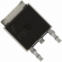
FDD6635 Fairchild Semiconductor, FDD6635 Datasheet - Page 3
FDD6635
Manufacturer Part Number
FDD6635
Description
MOSFET N-CH 35V 15A DPAK
Manufacturer
Fairchild Semiconductor
Series
PowerTrench®r
Datasheet
1.FDD6635.pdf
(8 pages)
Specifications of FDD6635
Fet Type
MOSFET N-Channel, Metal Oxide
Fet Feature
Logic Level Gate
Rds On (max) @ Id, Vgs
10 mOhm @ 15A, 10V
Drain To Source Voltage (vdss)
35V
Current - Continuous Drain (id) @ 25° C
15A
Vgs(th) (max) @ Id
3V @ 250µA
Gate Charge (qg) @ Vgs
36nC @ 10V
Input Capacitance (ciss) @ Vds
1400pF @ 20V
Power - Max
1.6W
Mounting Type
Surface Mount
Package / Case
DPak, TO-252 (2 leads+tab), SC-63
Configuration
Single
Transistor Polarity
N-Channel
Resistance Drain-source Rds (on)
0.01 Ohms
Drain-source Breakdown Voltage
35 V
Gate-source Breakdown Voltage
+/- 20 V
Continuous Drain Current
59 A
Power Dissipation
55 W
Maximum Operating Temperature
+ 150 C
Mounting Style
SMD/SMT
Minimum Operating Temperature
- 55 C
Lead Free Status / RoHS Status
Lead free / RoHS Compliant
Other names
FDD6635TR
Available stocks
Company
Part Number
Manufacturer
Quantity
Price
Company:

Part Number:
FDD6635
Manufacturer:
FAIRCHILD
Quantity:
35 000
Company:
Part Number:
FDD6635
Manufacturer:
FAIRCHILD
Quantity:
8 200


Notes:
1. R
2. Pulse Test: Pulse Width < 300μs, Duty Cycle < 2.0%
3. Maximum current is calculated as:
4. BV(avalanche) Single-Pulse rating is guaranteed if device is operated within the UIS SOA boundary of the device.
5. Starting T
FDD6635 Rev. C2(W)
Electrical Characteristics
Symbol
Drain–Source Diode Characteristics
V
trr
Qrr
the drain pins. R
Scale 1 : 1 on letter size paper
where P
SD
θJA
is the sum of the junction-to-case and case-to-ambient thermal resistance where the case thermal reference is defined as the solder mounting surface of
D
J
is maximum power dissipation at T
= 25°C, L = 1mH, I
θJC
Drain–Source Diode Forward
Voltage
Diode Reverse Recovery Time
Diode Reverse Recovery Charge
is guaranteed by design while R
AS
Parameter
= 15A, V
DD
= 35V, V
C
R
a) R
P
= 25°C and R
DS(ON)
D
1in
θJA
θCA
2
GS
pad of 2 oz copper
= 40°C/W when mounted on a
is determined by the user's board design.
= 10V
DS(on)
V
IF = 15 A,
is at T
T
A
GS
= 25°C unless otherwise noted
= 0 V,
J(max)
Test Conditions
and V
I
diF/dt = 100 A/µs
GS
S
= 15 A
= 10V. Package current limitation is 21A
(Note 2)
b) R
Min Typ Max Units
on a minimum pad.
θJA
= 96°C/W when mounted
0.8
26
16
www.fairchildsemi.com
1.2
nC
ns
V
Related parts for FDD6635
Image
Part Number
Description
Manufacturer
Datasheet
Request
R

Part Number:
Description:
Fairchild Semiconductor [IGBT MODULE]
Manufacturer:
Fairchild Semiconductor
Datasheet:

Part Number:
Description:
Discrete Semiconductor Modules
Manufacturer:
Fairchild Semiconductor
Part Number:
Description:
Discrete Semiconductor Modules
Manufacturer:
Fairchild Semiconductor
Part Number:
Description:
This N-Channel MOSFET is produced using Fairchild Semiconductor’s advanced Power Trench® process
Manufacturer:
Fairchild Semiconductor
Datasheet:
Part Number:
Description:
This N-Channel MOSFET is produced using Fairchild Semiconductor’s advanced Power Trench® process
Manufacturer:
Fairchild Semiconductor
Datasheet:
Part Number:
Description:
This N-Channel MOSFET is produced using Fairchild Semiconductor’s advanced PowerTrench® process
Manufacturer:
Fairchild Semiconductor
Datasheet:
Part Number:
Description:
This N-Channel MOSFET is produced using Fairchild Semiconductor’s advanced PowerTrench® process
Manufacturer:
Fairchild Semiconductor
Datasheet:
Part Number:
Description:
This N-Channel MOSFET is produced using Fairchild Semiconductor’s advanced Power Trench® process
Manufacturer:
Fairchild Semiconductor
Datasheet:
Part Number:
Description:
This N-Channel logic Level MOSFETs are produced using Fairchild Semiconductor‘s advanced Power Trench® process that has been special tailored to minimize the on-state resistance and yet maintain superior switching performance
Manufacturer:
Fairchild Semiconductor
Datasheet:
Part Number:
Description:
This N-Channel MOSFET is produced using Fairchild Semiconductor’s advanced Power Trench® process
Manufacturer:
Fairchild Semiconductor
Datasheet:
Part Number:
Description:
This N-Channel SyncFET™ is produced using Fairchild Semiconductor’s advanced PowerTrench® process
Manufacturer:
Fairchild Semiconductor
Datasheet:
Part Number:
Description:
This N-Channel SyncFET™ is produced using Fairchild Semiconductor’s advanced PowerTrench® process
Manufacturer:
Fairchild Semiconductor
Datasheet:
Part Number:
Description:
This N-Channel SyncFET™ is produced using Fairchild Semiconductor’s advanced PowerTrench® process
Manufacturer:
Fairchild Semiconductor
Datasheet:
Part Number:
Description:
This N-Channel logic Level MOSFETs are produced using Fairchild Semiconductor‘s advanced Power Trench® process that has been special tailored to minimize the on-state resistance and yet maintain superior switching performance
Manufacturer:
Fairchild Semiconductor
Datasheet:
Part Number:
Description:
This N-Channel MOSFET is produced using Fairchild Semiconductor’s advanced Power Trench® process that has been especially tailored to minimize the on-state resistance and yet maintain superior switching performance
Manufacturer:
Fairchild Semiconductor
Datasheet: