QB-MINI2-EE NEC, QB-MINI2-EE Datasheet - Page 16
QB-MINI2-EE
Manufacturer Part Number
QB-MINI2-EE
Description
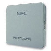
EMULATOR, PROGRAMMER, MINICUBE2
Manufacturer
NEC
Type
Debug Emulatorr
Datasheet
1.QB-MINI2-EE.pdf
(169 pages)
Specifications of QB-MINI2-EE
Svhc
No SVHC (18-Jun-2010)
Mcu Supported Families
MINICUBE2
Silicon Family Name
V850, 78K0R, 78K0S
Ic Product Type
On-Chip Debug Emulator
Kit Contents
MINICUBE2, USB Cable, Target Cable, 78K0-OCD Board
Features
On-Chip Debugging, Flash Memory Programming,


2. 3 Part Names and Functions of 78K0-OCD Board
16
(1) CLK1
(2) CN1
(3) CN2
(4) CN3
2-3 illustrates the external view of the 78K0-OCD board. The name of each part is printed on the 78K0-OCD
board. For each function, refer to (1) to (4), below.
For clock supply to the target device, a 14-pin DIP socket is implemented as CLK1. A 14-pin type oscillator (5
V) or a parts board that can configure an oscillation circuit can be mounted on the 14-pin DIP socket. A parts
board such as the 160-90-314 (manufactured by PRECI-DIP) can be used with this socket to configure
oscillation circuit.
This is a connector used to connect MINICUBE2 with the target interface connector of MINICUBE2. To
prevent the 78K0-OCD board from being inserted by mistake, a dummy pin is mounted in the place of pin 11 in
CN1.
This is a connector used to connect MINICUBE2 with the target system, via a 10-pin target cable.
A 10-core 2.54 mm pitch general-purpose connector (TSM-105-01-L-DV) is employed.
This is a connector used to connect MINICUBE2 with the target system, via a 16-pin target cable.
A 16-core 2.54 mm pitch general-purpose connector (TSM-108-01-L-DV) is employed.
The 78K0-OCD board is used for debugging a 78K0 microcontroller (not used for flash programming). Figure
CHAPTER 2
Figure 2-3. Part Names of 78K0-OCD Board
User’s Manual U18371EJ1V0UM
NAMES AND FUNCTIONS OF HARDWARE
Related parts for QB-MINI2-EE
Image
Part Number
Description
Manufacturer
Datasheet
Request
R

Part Number:
Description:
16/8 bit single-chip microcomputer
Manufacturer:
NEC
Datasheet:
Part Number:
Description:
Dual audio power amp circuit
Manufacturer:
NEC
Datasheet:
Part Number:
Description:
Dual comparator
Manufacturer:
NEC
Datasheet:
Part Number:
Description:
MOS type composite field effect transistor
Manufacturer:
NEC
Datasheet:
Part Number:
Description:
50 V/100 mA FET array incorporating 2 N-ch MOSFETs
Manufacturer:
NEC
Datasheet:
Part Number:
Description:
6-pin small MM high-frequency double transistor
Manufacturer:
NEC
Datasheet:
Part Number:
Description:
6-pin small MM high-frequency double transistor
Manufacturer:
NEC
Datasheet:
Part Number:
Description:
6-pin small MM high-frequency double transistor
Manufacturer:
NEC
Datasheet:
Part Number:
Description:
6-pin small MM high-frequency double transistor
Manufacturer:
NEC
Datasheet:
Part Number:
Description:
Twin transistors equipped with different model chips(6P small MM)
Manufacturer:
NEC
Datasheet:
Part Number:
Description:
Bipolar analog integrated circuit
Manufacturer:
NEC
Datasheet: