QB-MINI2-EE NEC, QB-MINI2-EE Datasheet - Page 121
QB-MINI2-EE
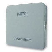
Manufacturer Part Number
QB-MINI2-EE
Description
EMULATOR, PROGRAMMER, MINICUBE2
Manufacturer
NEC
Type
Debug Emulatorr
Datasheet
1.QB-MINI2-EE.pdf
(169 pages)
Specifications of QB-MINI2-EE
Svhc
No SVHC (18-Jun-2010)
Mcu Supported Families
MINICUBE2
Silicon Family Name
V850, 78K0R, 78K0S
Ic Product Type
On-Chip Debug Emulator
Kit Contents
MINICUBE2, USB Cable, Target Cable, 78K0-OCD Board
Features
On-Chip Debugging, Flash Memory Programming,


5.2.7 Cautions on debugging
(1) Handling of device that was used for debugging
(2) Cases where debugger operation speed is degraded
(3) Reset processing
(4) When breaks cannot be executed
(5) Flash self programming
(6) Operation after reset
This section describes cautions on performing on-chip debugging for a 78K0S microcontroller.
Be sure to read the following to use MINICUBE2 properly.
Do not mount a device that was used for debugging on a mass-produced product, because the flash memory
was rewritten during debugging and the number of rewrites of the flash memory cannot be guaranteed.
The debugger operation speed may be degraded when too many contents of the memory or registers are
displayed in a debugger window, particularly when using a host machine with a USB 1.1 interface.
The debugger response is also slowed while the flash memory is being overwritten.
This phenomenon may be improved to some extent by raising the CPU operation clock frequency, by setting
the PCC or PPCC register.
If the RESET pin of the target device alternately functions as a port, enable the RESET pin by the user
program settings, such as option byte setting.
Forced breaks cannot be executed if one of the following conditions is satisfied.
• Interrupts are disabled (DI)
• Interrupts issued for the INTP pin, which is used for communication between MINICUBE2 and the target
• The alternate-function port corresponding to the INTP pin is not set to the input mode
• The external interrupt edge corresponding to the INTP pin is not set to the rising edge
• Standby mode is entered while standby release by a maskable interrupt is prohibited
If a space where the debug monitor program is allocated is rewritten by flash self programming, the debugger
can no longer operate normally.
After an external pin reset or internal reset, the monitor program performs debug initialization processing.
Consequently, the time from reset occurrence until user program execution differs from that in the actual
device operation.
device, are masked
CHAPTER 5
HOW TO USE MINICUBE2 WITH 78K0S MICROCONTROLLER
User’s Manual U18371EJ1V0UM
121
Related parts for QB-MINI2-EE
Image
Part Number
Description
Manufacturer
Datasheet
Request
R

Part Number:
Description:
16/8 bit single-chip microcomputer
Manufacturer:
NEC
Datasheet:
Part Number:
Description:
Dual audio power amp circuit
Manufacturer:
NEC
Datasheet:
Part Number:
Description:
Dual comparator
Manufacturer:
NEC
Datasheet:
Part Number:
Description:
MOS type composite field effect transistor
Manufacturer:
NEC
Datasheet:
Part Number:
Description:
50 V/100 mA FET array incorporating 2 N-ch MOSFETs
Manufacturer:
NEC
Datasheet:
Part Number:
Description:
6-pin small MM high-frequency double transistor
Manufacturer:
NEC
Datasheet:
Part Number:
Description:
6-pin small MM high-frequency double transistor
Manufacturer:
NEC
Datasheet:
Part Number:
Description:
6-pin small MM high-frequency double transistor
Manufacturer:
NEC
Datasheet:
Part Number:
Description:
6-pin small MM high-frequency double transistor
Manufacturer:
NEC
Datasheet:
Part Number:
Description:
Twin transistors equipped with different model chips(6P small MM)
Manufacturer:
NEC
Datasheet:
Part Number:
Description:
Bipolar analog integrated circuit
Manufacturer:
NEC
Datasheet: