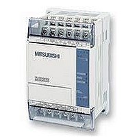
FX1S-30MR-ES/UL MITSUBISHI, FX1S-30MR-ES/UL Datasheet - Page 92

FX1S-30MR-ES/UL
Manufacturer Part Number
FX1S-30MR-ES/UL
Description
PLC, 16 IN, 14 RELAY OUT, 110V/2
Manufacturer
MITSUBISHI
Datasheet
1.FX1S-30MR-ESUL.pdf
(380 pages)
Specifications of FX1S-30MR-ES/UL
No. Of Analogue Inputs
16
No. Of Analogue Outputs
14
Ip/nema Rating
IP10
Approval Bodies
CE, CUL, UL
External Depth
49mm
External Length / Height
90mm
External Width
60mm
Mounting Type
Panel
- Current page: 92 of 380
- Download datasheet (7Mb)
4.9.4
4.9.5
FX Series Programmable Controllers
Timers Used in Interrupt and ‘CALL’ Subroutines
If timers T192 to T199 and T246 to T249 are used in a CALL subroutine or an interruption
routine, the timing action is updated at the point when an END instruction is executed. The
output contact is activated when a coil instruction or an END instruction is processed once the
timers current value has reached the preset (maximum duration) value.
Timers other than those specified above cannot function correctly within the specified
circumstances.
When an interrupt timer (1 msec resolution) is used in an interrupt routine or within a ‘CALL’
subroutine, the output contact is activated when the first coil instruction of that timer is
executed after the timer has reached its preset (maximum duration) value.
Timer Accuracy
Timer accuracy can be affected by the program configuration. That is to say, if a timer contact
is used before its associated coil, then the timer accuracy is reduced.
The following formulas give maximum and minimum errors for certain situations.
However, an average expected error would be approximately;
Condition 1:
The timer contact appears after the timer coil.
Maximum timing error:
Minimum timing error:
Condition 2:
The timer contact appears before the timer coil.
Maximum timing error:
Minimum timing error:
Internal timer accuracy:
• The actual accuracy of the timing elements within the PLC hardware is;
± 10 pulses per million pulses. This means that if a 100 msec timer is used to time a sin-
gle day, at the end of that day the timer will be within 0.8 seconds of the true 24 hours or
86,400 seconds. The timer would have processed approximately 864,000; 100 msec
pulses.
1.5
2
Input filter time - The timer resolution
3
Input filter time- The timer resolution
Scan time + The input filter time
Scan time + The input filter time
The program scan time
X10
X10
T0
T0
Devices in Detail 4
4-18
Y10
Y10
T0
T0
Related parts for FX1S-30MR-ES/UL
Image
Part Number
Description
Manufacturer
Datasheet
Request
R

Part Number:
Description:
MITSUBISHI IGBT MODULES
Manufacturer:
MITSUBISHI
Datasheet:

Part Number:
Description:
MITSUBISHI INTELLIGENT POWER MODULES
Manufacturer:
MITSUBISHI
Datasheet:

Part Number:
Description:
TRANSFER-MOLD TYPE INSULATED TYPE
Manufacturer:
MITSUBISHI
Datasheet:

Part Number:
Description:
Manufacturer:
MITSUBISHI
Datasheet:

Part Number:
Description:
30A intelligent power module for flat-base type
Manufacturer:
MITSUBISHI
Datasheet:

Part Number:
Description:
15A - transistor module for medium power switching use, insulated type
Manufacturer:
MITSUBISHI
Datasheet:

Part Number:
Description:
5A power module for transfer-mold type insulated type
Manufacturer:
MITSUBISHI
Datasheet:

Part Number:
Description:
30A intelligent power module for flat-base type
Manufacturer:
MITSUBISHI
Datasheet:

Part Number:
Description:
TRANSFER-MOLD TYPE INSULATED TYPE
Manufacturer:
MITSUBISHI
Datasheet:

Part Number:
Description:
TRANSFER-MOLD TYPE INSULATED TYPE
Manufacturer:
MITSUBISHI
Datasheet:

Part Number:
Description:
20A - transistor module for medium power switching use, insulated type
Manufacturer:
MITSUBISHI
Datasheet:

Part Number:
Description:
20A - transistor module for medium power switching use, insulated type
Manufacturer:
MITSUBISHI
Datasheet:


