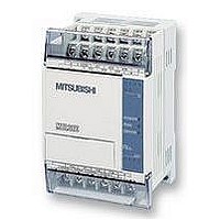
FX1S-30MR-ES/UL MITSUBISHI, FX1S-30MR-ES/UL Datasheet - Page 206

FX1S-30MR-ES/UL
Manufacturer Part Number
FX1S-30MR-ES/UL
Description
PLC, 16 IN, 14 RELAY OUT, 110V/2
Manufacturer
MITSUBISHI
Datasheet
1.FX1S-30MR-ESUL.pdf
(380 pages)
Specifications of FX1S-30MR-ES/UL
No. Of Analogue Inputs
16
No. Of Analogue Outputs
14
Ip/nema Rating
IP10
Approval Bodies
CE, CUL, UL
External Depth
49mm
External Length / Height
90mm
External Width
60mm
Mounting Type
Panel
- Current page: 206 of 380
- Download datasheet (7Mb)
5.8.4
FX Series Programmable Controlers
b) When n= 2, two sets of switches are read. This configuration requires 8 consecutive inputs
c) The outputs used for multiplexing (D
d) If the DSW instruction is suspended during mid-
e) It is recommended that transistor output units
f) The DSW instruction may be used TWICE on
SEGD (FNC 73)
SEGD
FNC 73
(Seven
segment
decoder)
Mnemonic
B4
B5 B6
taken from the head address specified in operand S. The data from the first set of switches,
i.e. those using the first 4 inputs, is read into data device D
of switches (again 4 digits) is read into data device D
cycled for as long as the DSW instruction is
driven. After the completion of one reading, the
execution complete flag M8029 is set. The
number of outputs used does not depend on
the number of switches n.
operation, when it is restarted it will start from
the beginning of its cycle and not from its last
status achieved.
are used with this instruction. However, if the
program technique at the right is used, relay
output units can be successfully operated as
the outputs will not be continually active.
FX
can operate an Unlimited number of DSW
instructions.
2N
B3
B0
& FX
B2
B1
Hex data is
decoded into a
format used to
drive seven
segment displays
2NC
It can be seen that
B 7 i s N O T u s e d .
H e n c e B 7 o f t h e
destination device D
will always be OFF,
Function
controllers. FX
K, H
KnX, KnY, KnM, KnS,
T, C, D, V, Z
Note: Uses only the
lower 4 bits
1S
& FX
S
1N
Operation:
A sin gle he xa de cim al dig it (0 to 9, A to F)
occupying the lower 4 bits of source device S is
decoded into a data format used to drive a seven
segment display. A representation of the hex digit
is then displayed. The decoded data is stored in
the lower 8 bits of destination device D. The upper
8 bits of the same device are not written to. The
diagram opposite shows the bit control of the
seven segment display. The active bits correspond
to th os e se t t o 1 in th e lo w er 8 b its o f th e
destination device D.
1
) are
units
Operands
KnY, KnM, KnS,
T, C, D, V, Z
Note: The upper 8 bits
remain unchanged
2+1
.
2
. The data from the second set
D
Applied Instructions 5
SEGD,
SEGDP:
5 steps
Program steps
5-84
Related parts for FX1S-30MR-ES/UL
Image
Part Number
Description
Manufacturer
Datasheet
Request
R

Part Number:
Description:
MITSUBISHI IGBT MODULES
Manufacturer:
MITSUBISHI
Datasheet:

Part Number:
Description:
MITSUBISHI INTELLIGENT POWER MODULES
Manufacturer:
MITSUBISHI
Datasheet:

Part Number:
Description:
TRANSFER-MOLD TYPE INSULATED TYPE
Manufacturer:
MITSUBISHI
Datasheet:

Part Number:
Description:
Manufacturer:
MITSUBISHI
Datasheet:

Part Number:
Description:
30A intelligent power module for flat-base type
Manufacturer:
MITSUBISHI
Datasheet:

Part Number:
Description:
15A - transistor module for medium power switching use, insulated type
Manufacturer:
MITSUBISHI
Datasheet:

Part Number:
Description:
5A power module for transfer-mold type insulated type
Manufacturer:
MITSUBISHI
Datasheet:

Part Number:
Description:
30A intelligent power module for flat-base type
Manufacturer:
MITSUBISHI
Datasheet:

Part Number:
Description:
TRANSFER-MOLD TYPE INSULATED TYPE
Manufacturer:
MITSUBISHI
Datasheet:

Part Number:
Description:
TRANSFER-MOLD TYPE INSULATED TYPE
Manufacturer:
MITSUBISHI
Datasheet:

Part Number:
Description:
20A - transistor module for medium power switching use, insulated type
Manufacturer:
MITSUBISHI
Datasheet:

Part Number:
Description:
20A - transistor module for medium power switching use, insulated type
Manufacturer:
MITSUBISHI
Datasheet:


