ADIS16400/PCBZ Analog Devices Inc, ADIS16400/PCBZ Datasheet - Page 8
ADIS16400/PCBZ
Manufacturer Part Number
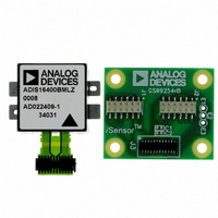
ADIS16400/PCBZ
Description
ADIS16400/PCB EVAL. BD. PB Free
Manufacturer
Analog Devices Inc
Series
iMEMS®, iSensor™r
Specifications of ADIS16400/PCBZ
Sensor Type
Accelerometer, Gyroscope, Magnetometer, 3 Axis
Sensing Range
±18g, ±75°/sec, ±150°/sec, ±300°/sec, ±2.5gauss
Interface
SPI Serial
Sensitivity
3.33mg/LSB, 0.0125 ~ 0.05°/sec/LSB, 0.5mgauss/LSB
Voltage - Supply
4.75 V ~ 5.25 V
Embedded
No
Utilized Ic / Part
ADIS16400
Silicon Manufacturer
Analog Devices
Silicon Core Number
ADIS16400
Kit Application Type
Sensing - Navigation / Position
Application Sub Type
Accelerometer / Gyroscope
Kit Contents
Board, Manual
Rohs Compliant
Yes
Lead Free Status / RoHS Status
Lead free / RoHS Compliant


ADIS16400/ADIS16405
PIN CONFIGURATION AND FUNCTION DESCRIPTIONS
Table 5. Pin Function Descriptions
Pin No.
1
2
16, 17, 18, 19, 22, 23, 24
3
4
5
6
7
8
9
10, 11, 12
13, 14, 15
20
21
1
S is supply, O is output, I is input, N/A is not applicable.
Mnemonic
DIO3
DIO4/CLKIN
DNC
SCLK
DOUT
DIN
CS
DIO1
RST
DIO2
VCC
GND
AUX_DAC
AUX_ADC
Y-AXIS
NOTES
1.
2.
3.
NOTES
1. THIS VIEW REPRESENTS THE TOP VIEW OF THE MATING CONNECTOR.
2. WHEN CONNECTED TO THE ADIS16400/ADIS16405, THE PINS ARE
3. MATING CONNECTOR: SAMTEC CLM-112-02 OR EQUIVALENT.
4. DNC = DO NOT CONNECT.
m
a
g
m
PRODUCES A POSITIVE OUTPUT.
PRODUCES A POSITIVE OUTPUT.
PRODUCES A POSITIVE OUTPUT.
X
PIN 23
X
NOT VISIBLE.
Y
X
,
,
,
a
g
m
Y
Y
,
,
a
Y
a
g
,
Y
g
Z
Z
m
Y
, ARROWS INDICATE THE DIRECTION OF ACCELERATION THAT
, ARROWS INDICATE THE DIRECTION OF ROTATION THAT
Z
PIN 1
1
2
, ARROWS INDICATE THE DIRECTION OF MAGNETIC FIELD THAT
3
4
5
6
I/O
Type
I/O
N/A
I
O
I
I
I/O
I
I/O
S
S
O
I
ADIS16400/ADIS16405
Figure 5. Pin Configuration
Figure 6. Axial Orientation
7
8
ORIGIN ALIGNMENT REFERENCE POINT
SEE MSC_CTRL[6].
a
1
Rev. B | Page 8 of 20
Z
10
9
(Not to Scale)
TOP VIEW
Z-AXIS
11
12
13
14
g
m
Z
15
16
Z
Description
Configurable Digital Input/Output.
Configurable Digital Input/Output or Sync Clock Input.
Do Not Connect.
SPI Serial Clock.
SPI Data Output. Clocks output on SCLK falling edge.
SPI Data Input. Clocks input on SCLK rising edge.
SPI Chip Select.
Configurable Digital Input/Output.
Reset.
Configurable Digital Input/Output.
Power Supply.
Power Ground.
Auxiliary, 12-Bit DAC Output.
Auxiliary, 12-Bit ADC Input.
17
18
19
20
21
22
23
24
g
m
X
X
X-AXIS
a
X
Related parts for ADIS16400/PCBZ
Image
Part Number
Description
Manufacturer
Datasheet
Request
R

Part Number:
Description:
±1.7g Dual-Axis IMEMS Accelerometer Evaluation Board
Manufacturer:
Analog Devices Inc
Datasheet:

Part Number:
Description:
Inertial Sensor Evaluation System
Manufacturer:
Analog Devices Inc
Datasheet:
Part Number:
Description:
Manufacturer:
Analog Devices Inc
Datasheet:
Part Number:
Description:
Manufacturer:
Analog Devices Inc
Datasheet:
Part Number:
Description:
Manufacturer:
Analog Devices Inc
Datasheet:
Part Number:
Description:
Manufacturer:
Analog Devices Inc
Datasheet:
Part Number:
Description:
Manufacturer:
Analog Devices Inc
Datasheet:
Part Number:
Description:
Manufacturer:
Analog Devices Inc
Datasheet:
Part Number:
Description:
Manufacturer:
Analog Devices Inc
Datasheet:
Part Number:
Description:
Manufacturer:
Analog Devices Inc
Datasheet:
Part Number:
Description:
Manufacturer:
Analog Devices Inc
Datasheet:
Part Number:
Description:
Manufacturer:
Analog Devices Inc
Datasheet:
Part Number:
Description:
Manufacturer:
Analog Devices Inc
Datasheet: