ADIS16400/PCBZ Analog Devices Inc, ADIS16400/PCBZ Datasheet - Page 16
ADIS16400/PCBZ
Manufacturer Part Number
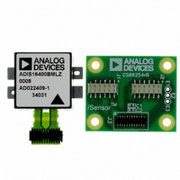
ADIS16400/PCBZ
Description
ADIS16400/PCB EVAL. BD. PB Free
Manufacturer
Analog Devices Inc
Series
iMEMS®, iSensor™r
Specifications of ADIS16400/PCBZ
Sensor Type
Accelerometer, Gyroscope, Magnetometer, 3 Axis
Sensing Range
±18g, ±75°/sec, ±150°/sec, ±300°/sec, ±2.5gauss
Interface
SPI Serial
Sensitivity
3.33mg/LSB, 0.0125 ~ 0.05°/sec/LSB, 0.5mgauss/LSB
Voltage - Supply
4.75 V ~ 5.25 V
Embedded
No
Utilized Ic / Part
ADIS16400
Silicon Manufacturer
Analog Devices
Silicon Core Number
ADIS16400
Kit Application Type
Sensing - Navigation / Position
Application Sub Type
Accelerometer / Gyroscope
Kit Contents
Board, Manual
Rohs Compliant
Yes
Lead Free Status / RoHS Status
Lead free / RoHS Compliant


ADIS16400/ADIS16405
Alarm Registers
The alarm function provides monitoring for two independent
conditions. The ALM_CTRL register provides control inputs
for data source, data filtering (prior to comparison), static
comparison, dynamic rate-of-change comparison, and output
indicator configurations. The ALM_MAGx registers establish the
trigger threshold and polarity configurations.
Table 27 gives an example of how to configure a static alarm.
The ALM_SMPLx registers provide the number of samples to
use in the dynamic rate-of-change configuration. The period
equals the number in the ALM_SMPLx register multiplied by
the sample period time, which is established by the SMPL_PRD
register. See Table 28 for an example of how to configure the
sensor for this type of function.
Table 24. ALM_CTRL Bit Designations
Bits
[15:12]
[11:8]
[7]
[6]
[5]
[4]
[3]
[2]
[1]
[0]
Settings
0000
0001
0010
0011
0100
0101
0110
0111
1000
1001
1010
1011
1100
Description
Alarm 2 source selection
Disable
Power supply output
X-axis gyroscope output
Y-axis gyroscope output
Z-axis gyroscope output
X-axis accelerometer output
Y-axis accelerometer output
Z-axis accelerometer output
X-axis magnetometer output
Y-axis magnetometer output
Z-axis magnetometer output
Gyroscope temperature output
Auxiliary ADC input
Alarm 1 source selection (same as Alarm 2)
Rate-of-change (ROC) enable for Alarm 2
1 = rate of change, 0 = static level
Rate-of-change (ROC) enable for Alarm 1
1 = rate of change, 0 = static level
Not used
Comparison data filter setting
1 = filtered data, 0 = unfiltered data
Not used
Alarm output enable
1 = enabled, 0 = disabled
Alarm output polarity
1 = active high, 0 = active low
Alarm output line select
1 = DIO2, 0 = DIO1
Default = 0x0000
Rev. B | Page 16 of 20
Table 25. ALM_MAG1, ALM_MAG2
Bits
[15]
[14]
[13:0]
Table 26. ALM_SMPL1, ALM_SMPL2
Bits
[15:8]
[7:0]
Table 27. Alarm Configuration Example 1
DIN
0xAF55,
0xAE17
0xA783,
0xA641
0xA93C,
0xA8BF
Table 28. Alarm Configuration Example 2
DIN
0xAF76,
0xAE87
0xB601
0xAB08
0xAC50
0xA783,
0xA641
0xA93C,
0xA8BE
Description
Comparison polarity
1 = greater than, 0 = less than
Not used
Data bits that match the format of the trigger
source selection
Description
Not used
Data bits: number of samples
(both 0x00 and 0x01 = 1)
Description
ALM_CTRL = 0x5517.
Alarm 1 input = XACCL_OUT.
Alarm 2 input = XACCL_OUT.
Static level comparison, filtered data.
DIO2 output indicator, positive polarity.
ALM_MAG1 = 0x8341.
Alarm 1 is true if XACCL_OUT > +0.5 g.
ALM_MAG2= 0x3CBF.
Alarm 2 is true if XACCL_OUT < −0.5 g.
Description
ALM_CTRL = 0x7687.
Alarm 1 input = ZACCL_OUT.
Alarm 2 input = YACCL_OUT.
Rate of change comparison, unfiltered data.
DIO2 output indicator, positive polarity.
SMPL_PRD = 0x0001.
Sample rate = 819.2 SPS.
ALM_SMPL1 = 0x0008.
Alarm 1 rate of change period = 9.77 ms.
ALM_SMPL2= 0x0050.
Alarm 2 rate of change period = 97.7 ms.
ALM_MAG1 = 0x8341.
Alarm 1 is true if XACCL_OUT > +0.5 g.
ALM_MAG2= 0x3CBE.
Alarm 2 is true if XACCL_OUT < −0.5 g.
Default = 0x0000
Default = 0x0000
Related parts for ADIS16400/PCBZ
Image
Part Number
Description
Manufacturer
Datasheet
Request
R

Part Number:
Description:
±1.7g Dual-Axis IMEMS Accelerometer Evaluation Board
Manufacturer:
Analog Devices Inc
Datasheet:

Part Number:
Description:
Inertial Sensor Evaluation System
Manufacturer:
Analog Devices Inc
Datasheet:
Part Number:
Description:
Manufacturer:
Analog Devices Inc
Datasheet:
Part Number:
Description:
Manufacturer:
Analog Devices Inc
Datasheet:
Part Number:
Description:
Manufacturer:
Analog Devices Inc
Datasheet:
Part Number:
Description:
Manufacturer:
Analog Devices Inc
Datasheet:
Part Number:
Description:
Manufacturer:
Analog Devices Inc
Datasheet:
Part Number:
Description:
Manufacturer:
Analog Devices Inc
Datasheet:
Part Number:
Description:
Manufacturer:
Analog Devices Inc
Datasheet:
Part Number:
Description:
Manufacturer:
Analog Devices Inc
Datasheet:
Part Number:
Description:
Manufacturer:
Analog Devices Inc
Datasheet:
Part Number:
Description:
Manufacturer:
Analog Devices Inc
Datasheet:
Part Number:
Description:
Manufacturer:
Analog Devices Inc
Datasheet: