ADIS16400/PCBZ Analog Devices Inc, ADIS16400/PCBZ Datasheet - Page 2
ADIS16400/PCBZ
Manufacturer Part Number
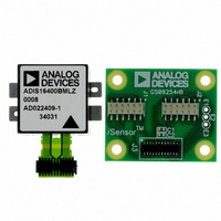
ADIS16400/PCBZ
Description
ADIS16400/PCB EVAL. BD. PB Free
Manufacturer
Analog Devices Inc
Series
iMEMS®, iSensor™r
Specifications of ADIS16400/PCBZ
Sensor Type
Accelerometer, Gyroscope, Magnetometer, 3 Axis
Sensing Range
±18g, ±75°/sec, ±150°/sec, ±300°/sec, ±2.5gauss
Interface
SPI Serial
Sensitivity
3.33mg/LSB, 0.0125 ~ 0.05°/sec/LSB, 0.5mgauss/LSB
Voltage - Supply
4.75 V ~ 5.25 V
Embedded
No
Utilized Ic / Part
ADIS16400
Silicon Manufacturer
Analog Devices
Silicon Core Number
ADIS16400
Kit Application Type
Sensing - Navigation / Position
Application Sub Type
Accelerometer / Gyroscope
Kit Contents
Board, Manual
Rohs Compliant
Yes
Lead Free Status / RoHS Status
Lead free / RoHS Compliant


ADIS16400/ADIS16405
TABLE OF CONTENTS
Features .............................................................................................. 1
Applications ....................................................................................... 1
Functional Block Diagram .............................................................. 1
General Description ......................................................................... 1
Revision History ............................................................................... 2
Specifications ..................................................................................... 3
Absolute Maximum Ratings ............................................................ 7
Pin Configuration and Function Descriptions ............................. 8
Typical Performance Characteristics ............................................. 9
Theory of Operation ...................................................................... 10
REVISION HISTORY
7/09—Rev. A to Rev. B
Changes to Features Section............................................................ 1
Changes to Data Retention Parameter ........................................... 4
Changes to Table 2 ............................................................................ 6
Changes to Figure 6 .......................................................................... 8
Changes to Device Configuration Section .................................. 10
Changes to Table 8 .......................................................................... 11
Changes to Table 9 and Added Default Value to Table 10,
Table 11, and Table 12 .................................................................... 12
Added Default Value to Table 13, and Table 15 and changes to
Internal Sample Rate Section and Table 15 ................................. 13
Added Default Value to Table 17, Table 18, and Table 19 and
Changes to Digital Filtering Section ............................................ 14
Added Default Value to Table 20 and Changes to Table 23 ...... 15
Added Default Value to Table 24, Table 25, and Table 26 and
Changes to Table 24 ........................................................................ 16
Changes to Ordering Guide .......................................................... 18
Timing Specifications .................................................................. 6
Timing Diagrams .......................................................................... 6
ESD Caution .................................................................................. 7
Rev. B | Page 2 of 20
Outline Dimensions ....................................................................... 17
4/09—Rev. 0 to Rev. A
Added ADIS16400 .............................................................. Universal
Changes to Features .......................................................................... 1
Changes to Table 1 ............................................................................. 3
Changes to Figure 5 and Figure 6 .................................................... 8
Changes to Reading Sensor Data Section ................................... 10
Changes to Internal Sample Rate Section ................................... 13
Changes to Input/Output Functions Section .............................. 14
Changes to Digital Filtering Section ............................................ 14
Changes to Ordering Guide .......................................................... 17
3/09—Revision 0: Initial Version
Basic Operation .......................................................................... 10
Reading Sensor Data .................................................................. 10
Device Configuration ................................................................ 10
Burst Mode Data Collection ..................................................... 10
Memory Map .............................................................................. 11
Output Data Registers ............................................................... 12
Calibration ................................................................................... 12
Operational Control ................................................................... 13
Input/Output Functions ............................................................ 14
Diagnostics .................................................................................. 15
Ordering Guide .......................................................................... 17
Related parts for ADIS16400/PCBZ
Image
Part Number
Description
Manufacturer
Datasheet
Request
R

Part Number:
Description:
±1.7g Dual-Axis IMEMS Accelerometer Evaluation Board
Manufacturer:
Analog Devices Inc
Datasheet:

Part Number:
Description:
Inertial Sensor Evaluation System
Manufacturer:
Analog Devices Inc
Datasheet:
Part Number:
Description:
Manufacturer:
Analog Devices Inc
Datasheet:
Part Number:
Description:
Manufacturer:
Analog Devices Inc
Datasheet:
Part Number:
Description:
Manufacturer:
Analog Devices Inc
Datasheet:
Part Number:
Description:
Manufacturer:
Analog Devices Inc
Datasheet:
Part Number:
Description:
Manufacturer:
Analog Devices Inc
Datasheet:
Part Number:
Description:
Manufacturer:
Analog Devices Inc
Datasheet:
Part Number:
Description:
Manufacturer:
Analog Devices Inc
Datasheet:
Part Number:
Description:
Manufacturer:
Analog Devices Inc
Datasheet:
Part Number:
Description:
Manufacturer:
Analog Devices Inc
Datasheet:
Part Number:
Description:
Manufacturer:
Analog Devices Inc
Datasheet:
Part Number:
Description:
Manufacturer:
Analog Devices Inc
Datasheet: