ADIS16400/PCBZ Analog Devices Inc, ADIS16400/PCBZ Datasheet - Page 14
ADIS16400/PCBZ
Manufacturer Part Number
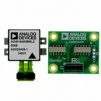
ADIS16400/PCBZ
Description
ADIS16400/PCB EVAL. BD. PB Free
Manufacturer
Analog Devices Inc
Series
iMEMS®, iSensor™r
Specifications of ADIS16400/PCBZ
Sensor Type
Accelerometer, Gyroscope, Magnetometer, 3 Axis
Sensing Range
±18g, ±75°/sec, ±150°/sec, ±300°/sec, ±2.5gauss
Interface
SPI Serial
Sensitivity
3.33mg/LSB, 0.0125 ~ 0.05°/sec/LSB, 0.5mgauss/LSB
Voltage - Supply
4.75 V ~ 5.25 V
Embedded
No
Utilized Ic / Part
ADIS16400
Silicon Manufacturer
Analog Devices
Silicon Core Number
ADIS16400
Kit Application Type
Sensing - Navigation / Position
Application Sub Type
Accelerometer / Gyroscope
Kit Contents
Board, Manual
Rohs Compliant
Yes
Lead Free Status / RoHS Status
Lead free / RoHS Compliant


ADIS16400/ADIS16405
Digital Filtering
A programmable low-pass filter provides additional opportunity
for noise reduction on the inertial sensor outputs. This filter
contains two cascaded averaging filters that provide a Bartlett
window, FIR filter response (see Figure 15). For example,
SENS_AVG[2:0] = 100 (DIN = B804) sets each stage tap to 16.
When used with the default sample rate of 819.2 SPS, this
reduces the sensor bandwidth to approximately 16 Hz.
Dynamic Range
There are three dynamic range settings for the gyroscope. The
lower dynamic range settings (±75°/sec and ±150°/sec) limit the
minimum filter tap sizes to maintain resolution. For example, set
SENS_AVG[10:8] = 010 (DIN = 0xB902) for a measurement
range of ±150°/sec. Because this setting can influence the filter
settings, program SENS_AVG[10:8], then SENS_AVG[2:0] if
more filtering is required.
Table 17. SENS_AVG
Bits
[15:11]
[10:8]
[7:3]
[2:0]
INPUT/OUTPUT FUNCTIONS
General-Purpose I/O
DIO1, DIO2, DIO3, and DIO4 are configurable, general-
purpose I/O lines that serve multiple purposes according to the
following control register priority: MSC_CTRL, ALM_CTRL,
and GPIO_CTRL. For example, set GPIO_CTRL = 0x080C
(DIN = 0xB308, and then 0xB20C) to set DIO1 and DIO2 as
inputs and DIO3 and DIO4 as outputs, with DIO3 set low and
DIO4 set high.
–100
–120
–140
–20
–40
–60
–80
0.001
0
Settings
100
010
001
Figure 15. Bartlett Window FIR Frequency Response
N = 2
N = 4
N = 16
N = 64
(Taps = 2N + 1, Phase = N Samples)
0.01
Description
Not used
Measurement range (sensitivity) selection
±300°/sec (default condition)
±150°/sec, filter taps ≥ 4 (Bits[2:0] ≥ 0x02)
±75°/sec, filter taps ≥ 16 (Bits[2:0] ≥ 0x04)
Not used
Number of taps in each stage N = 2
FREQUENCY (
f
/
f
S
)
0.1
Default = 0x0402
1
M
Rev. B | Page 14 of 20
Table 18. GPIO_CTRL
Bits
[15:12]
[11]
[10]
[9]
[8]
[7:4]
[3]
[2]
[1]
[0]
Input Clock Configuration
The input clock allows for external control over sampling in the
ADIS16400/ADIS16405. Set GPIO_CTRL[3] = 0 (DIN =
0x0B200) and SMPL_PRD[7:0] = 0x00 (DIN = 0xB600) to enable
this function. See Table 2 and Figure 4 for timing information.
Data Ready I/O Indicator
The factory default sets DIO1 as a positive data ready indicator
signal. The MSC_CTRL[2:0] register provides configuration
options for changing this. For example, set MSC_CTRL[2:0] =
100 (DIN = 0xB404) to change the polarity of the data ready
signal for interrupt inputs that require negative logic inputs for
activation. The resulting pulse width is be between 100 μs and
200 μs over all conditions.
Table 19. MSC_CTRL
Bits
[15:12]
[11]
[10]
[9]
[8]
[7]
[6]
[5:3]
[2]
[1]
[0]
Description
Not used
General-Purpose I/O Line 4 (DIO4) data level
General-Purpose I/O Line 3 (DIO3) data level
General-Purpose I/O Line 2 (DIO2) data level
General-Purpose I/O Line 1 (DIO1) data level
Not used
General-Purpose I/O Line 4 (DIO4), direction control
1 = output, 0 = input
General-Purpose I/O Line 3 (DIO3), direction control
1 = output, 0 = input
General-Purpose I/O Line 2 (DIO2), direction control
1 = output, 0 = input
General-Purpose I/O Line 1 (DIO1), direction control
1 = output, 0 = input
Description
Not used
Memory test (clears on completion)
1 = enabled, 0 = disabled
Internal self-test enable (clears on completion)
1 = enabled, 0 = disabled
Manual self-test, negative stimulus
1 = enabled, 0 = disabled
Manual self-test, positive stimulus
1 = enabled, 0 = disabled
Linear acceleration bias compensation for gyroscopes
1 = enabled, 0 = disabled
Linear accelerometer origin alignment
1 = enabled, 0 = disabled
Not used
Data ready enable
1 = enabled, 0 = disabled
Data ready polarity
1 = active high, 0 = active low
Data ready line select
1 = DIO2, 0 = DIO1
Default = 0x0000
Default = 0x0006
Related parts for ADIS16400/PCBZ
Image
Part Number
Description
Manufacturer
Datasheet
Request
R

Part Number:
Description:
±1.7g Dual-Axis IMEMS Accelerometer Evaluation Board
Manufacturer:
Analog Devices Inc
Datasheet:

Part Number:
Description:
Inertial Sensor Evaluation System
Manufacturer:
Analog Devices Inc
Datasheet:
Part Number:
Description:
Manufacturer:
Analog Devices Inc
Datasheet:
Part Number:
Description:
Manufacturer:
Analog Devices Inc
Datasheet:
Part Number:
Description:
Manufacturer:
Analog Devices Inc
Datasheet:
Part Number:
Description:
Manufacturer:
Analog Devices Inc
Datasheet:
Part Number:
Description:
Manufacturer:
Analog Devices Inc
Datasheet:
Part Number:
Description:
Manufacturer:
Analog Devices Inc
Datasheet:
Part Number:
Description:
Manufacturer:
Analog Devices Inc
Datasheet:
Part Number:
Description:
Manufacturer:
Analog Devices Inc
Datasheet:
Part Number:
Description:
Manufacturer:
Analog Devices Inc
Datasheet:
Part Number:
Description:
Manufacturer:
Analog Devices Inc
Datasheet:
Part Number:
Description:
Manufacturer:
Analog Devices Inc
Datasheet: