ADIS16400/PCBZ Analog Devices Inc, ADIS16400/PCBZ Datasheet - Page 15
ADIS16400/PCBZ
Manufacturer Part Number
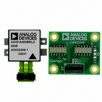
ADIS16400/PCBZ
Description
ADIS16400/PCB EVAL. BD. PB Free
Manufacturer
Analog Devices Inc
Series
iMEMS®, iSensor™r
Specifications of ADIS16400/PCBZ
Sensor Type
Accelerometer, Gyroscope, Magnetometer, 3 Axis
Sensing Range
±18g, ±75°/sec, ±150°/sec, ±300°/sec, ±2.5gauss
Interface
SPI Serial
Sensitivity
3.33mg/LSB, 0.0125 ~ 0.05°/sec/LSB, 0.5mgauss/LSB
Voltage - Supply
4.75 V ~ 5.25 V
Embedded
No
Utilized Ic / Part
ADIS16400
Silicon Manufacturer
Analog Devices
Silicon Core Number
ADIS16400
Kit Application Type
Sensing - Navigation / Position
Application Sub Type
Accelerometer / Gyroscope
Kit Contents
Board, Manual
Rohs Compliant
Yes
Lead Free Status / RoHS Status
Lead free / RoHS Compliant


Auxiliary DAC
The 12-bit AUX_DAC line can drive its output to within 5 mV
of the ground reference when it is not sinking current. As the
output approaches 0 V, the linearity begins to degrade (~100 LSB
beginning point). As the sink current increases, the nonlinear
range increases. The DAC latch command moves the values of
the AUX_DAC register into the DAC input register, enabling
both bytes to take effect at the same time.
Table 20. AUX_DAC
Bits
[15:12]
[11:0]
Table 21. Setting AUX_DAC = 1 V
DIN
0xB0D9
0xB104
0xBE04
DIAGNOSTICS
Self-Test
The self-test function offers the opportunity to verify the
mechanical integrity of each MEMS sensor. It applies an
electrostatic force to each sensor element, which results in
mechanical displacement that simulates a response to actual
motion. Table 1 lists the expected response for each sensor,
which provides pass/fail criteria. Set MSC_CTRL[10] = 1 (DIN
= 0xB504) to run the internal self-test routine, which exercises
all inertial sensors, measures each response, makes pass/fail
decisions, and reports them to error flags in the DIAG_STAT
register. MSC_CTRL[10] resets itself to 0 after completing the
routine. MSC_CTRL[9:8] (DIN = 0xB502 or 0xB501) provide
manual control over the self-test function. Table 22 shows an
example test flow for using this option to check the x-axis
gyroscope. Zero motion provides results that are more reliable.
The settings in Table 22 are flexible and provide opportunity for
optimization around speed and noise influence. For example,
using fewer filtering taps decreases delay times but increases the
opportunity for noise influence.
Memory Test
Setting MSC_CTRL[11] = 1 (DIN = 0xB508) performs a
checksum verification of the flash memory locations. The
pass/fail result loads into the DIAG_STAT[6] register.
Description
AUX_DAC[7:0] = 0xD9 (217 LSB).
AUX_DAC[15:8] = 0x04 (1024 LSB).
GLOB_CMD[2] = 1.
Move values into the DAC input register, resulting in
a 1 V output level.
Description
Not used.
Data bits. Scale factor = 0.8059 mV/code,
offset binary format, 0 V = 0 codes.
Default = 0x0000
Rev. B | Page 15 of 20
Status
The error flags provide indicator functions for common system-
level issues. All of the flags clear (set to 0) after each DIAG_STAT
register read cycle. If an error condition remains, the error flag
returns to 1 during the next sample cycle. DIAG_STAT[1:0]
does not require a read of this register to return to 0.
Table 22. Manual Self-Test Example Sequence
DIN
0xB601
0xB904
0xB802
0x0400
0xB502
0x0400
0xB501
0x0400
0xB500
Table 23. DIAG_STAT Bit Descriptions
Bit
[15]
[14]
[13]
[12]
[11]
[10]
[9]
[8]
[7]
[6]
[5]
[4]
[3]
[2]
[1]
[0]
Description
SMPL_PRD[7:0] = 0x01, sample rate = 819.2 SPS.
SENS_AVG[15:8] = 0x04, gyroscope range = ±300°/sec.
SENS_AVG[7:0] = 0x02, four-tap averaging filter.
Delay = 50 ms.
Read XGYRO_OUT.
MSC_CTRL[9] = 1, gyroscope negative self-test.
Delay = 50 ms.
Read XGYRO_OUT.
Calculate the positive change from the first reading to
the second reading of XGYRO_OUT, and check to
make sure the change is within the positive self-test
response range specified in Table 1.
MSC_CTRL[9:8] = 01, gyroscope/accelerometer
positive self-test.
Delay = 50 ms.
Read XGYRO_OUT.
Calculate the negative change from the first reading
to the third reading of XGYRO_OUT, and check to
make sure the change is within the positive self-test
response range specified in Table 1.
MSC_CTRL[15:8] = 0x00.
Description
Z-axis accelerometer self-test failure (1 = fail, 0 = pass)
Y-axis accelerometer self-test failure (1 = fail, 0 = pass)
X-axis accelerometer self-test failure (1 = fail, 0 = pass)
Z-axis gyroscope self-test failure (1 = fail, 0 = pass)
Y-axis gyroscope self-test failure (1 = fail, 0 = pass)
X-axis gyroscope self-test failure (1 = fail, 0 = pass)
Alarm 2 status (1 = active, 0 = inactive)
Alarm 1 status (1 = active, 0 = inactive)
Not used
Flash test, checksum flag (1 = fail, 0 = pass)
Self-test diagnostic error flag (1 = fail, 0 = pass)
Sensor overrange (1 = fail, 0 = pass)
SPI communication failure (1 = fail, 0 = pass)
Flash update failure (1 = fail, 0 = pass)
Power supply above 5.25 V
(1 = power supply ≥ 5.25 V, 0 = power supply ≤ 5.25 V)
Power supply below 4.75 V
(1 = power supply ≤ 4.75 V, 0 = power supply ≥ 4.75 V)
ADIS16400/ADIS16405
Related parts for ADIS16400/PCBZ
Image
Part Number
Description
Manufacturer
Datasheet
Request
R

Part Number:
Description:
±1.7g Dual-Axis IMEMS Accelerometer Evaluation Board
Manufacturer:
Analog Devices Inc
Datasheet:

Part Number:
Description:
Inertial Sensor Evaluation System
Manufacturer:
Analog Devices Inc
Datasheet:
Part Number:
Description:
Manufacturer:
Analog Devices Inc
Datasheet:
Part Number:
Description:
Manufacturer:
Analog Devices Inc
Datasheet:
Part Number:
Description:
Manufacturer:
Analog Devices Inc
Datasheet:
Part Number:
Description:
Manufacturer:
Analog Devices Inc
Datasheet:
Part Number:
Description:
Manufacturer:
Analog Devices Inc
Datasheet:
Part Number:
Description:
Manufacturer:
Analog Devices Inc
Datasheet:
Part Number:
Description:
Manufacturer:
Analog Devices Inc
Datasheet:
Part Number:
Description:
Manufacturer:
Analog Devices Inc
Datasheet:
Part Number:
Description:
Manufacturer:
Analog Devices Inc
Datasheet:
Part Number:
Description:
Manufacturer:
Analog Devices Inc
Datasheet:
Part Number:
Description:
Manufacturer:
Analog Devices Inc
Datasheet: