WI.232FHSS-250-R Radiotronix, WI.232FHSS-250-R Datasheet - Page 48
WI.232FHSS-250-R
Manufacturer Part Number
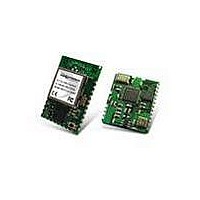
WI.232FHSS-250-R
Description
RF Modules & Development Tools 900MHz FHSS Low
Manufacturer
Radiotronix
Datasheet
1.WI.232FHSS-25-FCC-RA-R.pdf
(67 pages)
Specifications of WI.232FHSS-250-R
Lead Free Status / RoHS Status
Lead free / RoHS Compliant
Other names
WI232FHSS-250-R


WI.232FHSS-25-R/ WI.232FHSS-250-R DATASHEET
Default CMD Halt Setting: Disabled (0x00)
When configuring the module’s register settings, it is possible that incoming RF transmissions can intermix
with the command interpreter’s response, making it difficult to determine if your commands were
successfully processed. Changing this register setting to 0x01 will cause the module to store incoming RF
traffic (up to RF buffer overflow) while the CMD line is low. When the CMD pin is returned high, the RF
engine will send all buffered data to the UART. This feature is present in all Wi.232FHSS-250-R modules
and Wi.232FHSS-25(-R) modules with firmware version 1.0.4 or newer.
Default Receiver LNA Mode: High Sensitivity (Wi.232FHSS-25), AGC Enabled (Wi.232FHSS-250-R)
By default, the Wi.232FHSS-25 module is configured for maximum receiver sensitivity. Similarly, the
Wi.232FHSS-250-R is factory-configured to use its internal automatic gain control (AGC) circuit to manage
receiver sensitivity. Reducing the gain increases the linearity of the receiver, but reduces maximum
sensitivity; increasing the gain does the opposite. Generally speaking, higher linearity (increased third
order input intercept point, IIP3) will give improved performance in high-interference environments; high
gain yields better performance in low-interference environments.
The Wi.232FHSS-250-R contains an AGC circuit that manages these settings automatically, and it should
be used whenever possible. When reading the digital RSSI registers (regIMMEDRSSI, regLGPRSSI), the
internal calculation automatically compensates for the current LNA gain setting. However, when
attempting to make analog RSSI measurements, fixing the LNA gain will produce more meaningful results.
The following table summarizes the LNA settings for each of the modules.
Table 18, LNA Mode Settings
R/W
D7
7
R/W
D7
7
LNA
Mode
0x00
0x01
0x02
0x03
4.1.31. CMD Halts Traffic (regCMDHALT)
4.1.32. Receiver LNA Mode (regLNAMODE)
regNVLNAMODE (0x24)
regNVCMDHALT (0x23)
Meaning
High
Sensitivity
High Linearity
Invalid
Invalid
R/W
D6
6
R/W
D6
6
WI.232FHSS-25-R
IIP3 Increase
Reference
15 dB
N/A
N/A
R/W
D5
5
R/W
D5
5
R/W
D4
4
R/W
D4
4
Sensitivity
Decrease
Reference
10 dB
N/A
N/A
47
D3
3
D3
3
R/W
R/W
Meaning
AGC Enabled
High
Sensitivity
Mid Linearity
High Linearity
R/W
D2
2
R/W
D2
2
IIP3 Increase
Variable
Reference
19.1 dB
41.8 dB
WI.232FHSS-250-R
regCMDHALT (0x6E)
regLNAMODE (0x6F)
R/W
D1
1
R/W
D1
1
Sensitivity Decrease
Variable
Reference
6.5 dB
9.5 dB
Revision 1.1.0
R/W
D0
0
R/W
D0
0
Related parts for WI.232FHSS-250-R
Image
Part Number
Description
Manufacturer
Datasheet
Request
R

Part Number:
Description:
RF Modules & Development Tools WI.232FHSS-25-EVM-R EVALUATION MODULE
Manufacturer:
Radiotronix
Datasheet:
Part Number:
Description:
RF Modules & Development Tools 900MHz FHSS Low Power Transceiver
Manufacturer:
Radiotronix
Datasheet:
Part Number:
Description:
RF Modules & Development Tools 900MHz FHSS Low Power Transceiver
Manufacturer:
Radiotronix
Datasheet:
Part Number:
Description:
RF Modules & Development Tools 250mW module W/ right Angl SMA connt
Manufacturer:
Radiotronix
Datasheet:

Part Number:
Description:
RF Modules & Development Tools FCC Approved FHSS STRT ANT. JACK
Manufacturer:
Radiotronix
Datasheet:
Part Number:
Description:
RF Modules & Development Tools FCC Approved FHSS R/A ANT. JACK
Manufacturer:
Radiotronix
Datasheet:
Part Number:
Description:
RF Modules & Development Tools 250mW module
Manufacturer:
Radiotronix
Datasheet:
Part Number:
Description:
RF Modules & Development Tools 900MHz FHSS Low Power Transceiver
Manufacturer:
Radiotronix
Datasheet:
Part Number:
Description:
RF Modules & Development Tools Evaluation Module
Manufacturer:
Radiotronix
Datasheet:
Part Number:
Description:
RF Modules & Development Tools 250mW Mod w/ RPSMA Extended Connector
Manufacturer:
Radiotronix
Datasheet:
Part Number:
Description:
RF Modules & Development Tools 250mW Mod w/ RPSMA Extended Connector
Manufacturer:
Radiotronix
Datasheet:
Part Number:
Description:
RF Modules & Development Tools 900MHz FHSS Low Power Transceiver
Manufacturer:
Radiotronix
Datasheet:
Part Number:
Description:
RF Modules & Development Tools DEVELOPMENT KIT
Manufacturer:
Radiotronix
Datasheet:

Part Number:
Description:
DEVELOPMENT KIT
Manufacturer:
Radiotronix
Datasheet: