WI.232FHSS-250-R Radiotronix, WI.232FHSS-250-R Datasheet - Page 41
WI.232FHSS-250-R
Manufacturer Part Number
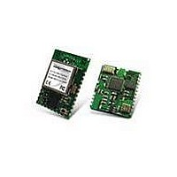
WI.232FHSS-250-R
Description
RF Modules & Development Tools 900MHz FHSS Low
Manufacturer
Radiotronix
Datasheet
1.WI.232FHSS-25-FCC-RA-R.pdf
(67 pages)
Specifications of WI.232FHSS-250-R
Lead Free Status / RoHS Status
Lead free / RoHS Compliant
Other names
WI232FHSS-250-R


WI.232FHSS-25-R/ WI.232FHSS-250-R DATASHEET
Default Operating mode: Awake (0x00)
Changing this register will place the register in the operating modes indicated in the table below. If the
module remains properly powered, and is awakened from Sleep, Standby, or Deep Sleep properly, the
volatile registers retain their values when awakened.
Awake mode is the normal operating mode. This is the only mode in which the RF circuitry is able to
receive and transmit RF messages.
Sleep and Standby are modes intended for legacy Wi.232DTS™ developers. Because the Wi.232FHSS-
25/250-R modules do not include the hardware to properly implement these two modes, current
consumption is much higher than in the Wi.233DTS™. For this reason, use of these two modes is not
recommended for new development. Standby leaves the RF oscillator circuit operating for faster wakeup,
whereas Sleep does not. In order to wake the module from these two modes, send one byte of 0x0F to the
module’s RxD pin (CMD left high) at the current baud rate. If
module will transmit a 0x06 byte through the TxD pin when the module is awake and ready to accept data
or commands.
Deep Sleep mode disables all circuitry on-board the module. This is the lowest-power mode available for
the module. When in Deep Sleep, the CTS pin is brought low, and both RF and microcontroller oscillators
are stopped. In order to wake the module, a negative-going pulse on the C2CK/RST pin of at least 15μs is
required. The module will begin the wake process once the C2CK/RST pin is returned high. If this line
experiences digital noise or glitching, it can cause multiple triggers (wake from sleep, hardware reset,
hardware reset, etc.). Multiple triggers can cause the reloading of volatile registers with their non-volatile
values. If your circuit introduces noise onto this pin, it should be filtered or bypassed with a capacitor to
ground or an RC filter.
If the volatile registers have been corrupted during sleep/standby/deep sleep, a software reset is forced
and the module will reboot. Possible causes of this are power surges or brownout. The module will
display the startup message (if not disabled in regNVSHOWVER), and send a 0x06 byte out the UART
TxD pin (if not disabled in regNVACKONWAKE) when the module is ready to accept commands and data.
Table 17, Operating Mode Register Settings
R/W
B7
7
Operating Mode
Awake
Sleep
Standby
Deep Sleep
4.1.12. Operating Mode (regOPMODE)
regNVOPMODE (0x0D)
R/W
B6
6
B1
0
0
1
1
R/W
B5
5
B0
0
1
0
1
R/W
B4
4
40
B3
3
R/W
regACKONWAKE
R/W
B2
2
regOPMODE (0x58)
is enabled (default), the
R/W
B1
1
Revision 1.1.0
R/W
B0
0
Related parts for WI.232FHSS-250-R
Image
Part Number
Description
Manufacturer
Datasheet
Request
R

Part Number:
Description:
RF Modules & Development Tools WI.232FHSS-25-EVM-R EVALUATION MODULE
Manufacturer:
Radiotronix
Datasheet:
Part Number:
Description:
RF Modules & Development Tools 900MHz FHSS Low Power Transceiver
Manufacturer:
Radiotronix
Datasheet:
Part Number:
Description:
RF Modules & Development Tools 900MHz FHSS Low Power Transceiver
Manufacturer:
Radiotronix
Datasheet:
Part Number:
Description:
RF Modules & Development Tools 250mW module W/ right Angl SMA connt
Manufacturer:
Radiotronix
Datasheet:

Part Number:
Description:
RF Modules & Development Tools FCC Approved FHSS STRT ANT. JACK
Manufacturer:
Radiotronix
Datasheet:
Part Number:
Description:
RF Modules & Development Tools FCC Approved FHSS R/A ANT. JACK
Manufacturer:
Radiotronix
Datasheet:
Part Number:
Description:
RF Modules & Development Tools 250mW module
Manufacturer:
Radiotronix
Datasheet:
Part Number:
Description:
RF Modules & Development Tools 900MHz FHSS Low Power Transceiver
Manufacturer:
Radiotronix
Datasheet:
Part Number:
Description:
RF Modules & Development Tools Evaluation Module
Manufacturer:
Radiotronix
Datasheet:
Part Number:
Description:
RF Modules & Development Tools 250mW Mod w/ RPSMA Extended Connector
Manufacturer:
Radiotronix
Datasheet:
Part Number:
Description:
RF Modules & Development Tools 250mW Mod w/ RPSMA Extended Connector
Manufacturer:
Radiotronix
Datasheet:
Part Number:
Description:
RF Modules & Development Tools 900MHz FHSS Low Power Transceiver
Manufacturer:
Radiotronix
Datasheet:
Part Number:
Description:
RF Modules & Development Tools DEVELOPMENT KIT
Manufacturer:
Radiotronix
Datasheet:

Part Number:
Description:
DEVELOPMENT KIT
Manufacturer:
Radiotronix
Datasheet: