WI.232FHSS-250-R Radiotronix, WI.232FHSS-250-R Datasheet - Page 28
WI.232FHSS-250-R
Manufacturer Part Number
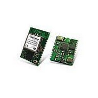
WI.232FHSS-250-R
Description
RF Modules & Development Tools 900MHz FHSS Low
Manufacturer
Radiotronix
Datasheet
1.WI.232FHSS-25-FCC-RA-R.pdf
(67 pages)
Specifications of WI.232FHSS-250-R
Lead Free Status / RoHS Status
Lead free / RoHS Compliant
Other names
WI232FHSS-250-R


WI.232FHSS-25-R/ WI.232FHSS-250-R DATASHEET
3.4. Power Supply
Although the Wi.232FHSS module is very easy to use, care must be given to the design of the power
supply circuit. It is important for the power supply to be free of digital noise generated by other parts of the
application circuit, such as the RS-232 converter.
Figure 11 shows the schematic for our evaluation module circuit for the Wi.232FHSS-25-R and
Wi.232FHSS-250-R modules. The EVM includes an on-board power supply and antenna connector.
These evaluation circuits were used to measure the performance of the Wi.232FHSS module, and should
be used as a reference for Wi.232FHSS based designs.
If noise is a problem, it can usually be eliminated by using a dedicated LDO regulator for the module and/or
by separating the grounds for the module and the other circuits.
Additionally, power supply rise time is extremely important. The power supply presented to the module
must rise from Vss to 2.7V in less than 1ms. If this specification cannot be met, an external reset
supervisor circuit must be used to hold the module in reset until the power supply stabilizes. Failure to
ensure adequate power supply rise time can result in loss of important module configuration
information.
The Wi.232FHSS-250-R module power supply should be bypassed as close to the module as possible for
maximum noise immunity (C1 and C2 in figure 11). Also, an inductor or ferrite choke may be placed close
to the module, in series with the supply line to further reduce any noise being conducted back onto the
supply from the module. Noise on the power supply can degrade receiver performance and cause other
instabilities.
3.5. UART Interface
The UART interface is very simple; it is comprised of four CMOS compatible digital lines.
Table 9, Wi.232FHSS-25–R and WI.232FHSS-250-R UART Interface Lines
Pin
CTS
CMD
RxD
TxD
RTS
Direction
Out
In
In
Out
In
Description
Clear to send – this pin indicates to the host micro when it is ok to send data.
When CTS is high, the host micro should stop sending data to the module
until CTS returns to the low state.
Command – the host micro will bring this pin low to put the module in
command mode. Command mode is used to set and read the internal
registers that control the operation of the module. When CMD is high, the
module will transparently transfer data to and from other modules on the
same channel.
Note:
registers will be reset to their factory programmed defaults. It is important to
ensure that CMD is held high or left floating during power-up under normal
conditions.
Receive data input. UART data should be sent to the module with no parity, 1
start bit, 1 stop bit, 8 data bits, least-significant bit first.
Transmit data output. UART data will be sent by the module with no parity, 1
start bit, 1 stop bit, 8 data bits, least-significant bit first.
Currently unimplemented, this pin is reserved for future use/reassignment.
If this pin is low when the module comes out of reset, the non-volatile
27
Revision 1.1.0
Related parts for WI.232FHSS-250-R
Image
Part Number
Description
Manufacturer
Datasheet
Request
R

Part Number:
Description:
RF Modules & Development Tools WI.232FHSS-25-EVM-R EVALUATION MODULE
Manufacturer:
Radiotronix
Datasheet:
Part Number:
Description:
RF Modules & Development Tools 900MHz FHSS Low Power Transceiver
Manufacturer:
Radiotronix
Datasheet:
Part Number:
Description:
RF Modules & Development Tools 900MHz FHSS Low Power Transceiver
Manufacturer:
Radiotronix
Datasheet:
Part Number:
Description:
RF Modules & Development Tools 250mW module W/ right Angl SMA connt
Manufacturer:
Radiotronix
Datasheet:

Part Number:
Description:
RF Modules & Development Tools FCC Approved FHSS STRT ANT. JACK
Manufacturer:
Radiotronix
Datasheet:
Part Number:
Description:
RF Modules & Development Tools FCC Approved FHSS R/A ANT. JACK
Manufacturer:
Radiotronix
Datasheet:
Part Number:
Description:
RF Modules & Development Tools 250mW module
Manufacturer:
Radiotronix
Datasheet:
Part Number:
Description:
RF Modules & Development Tools 900MHz FHSS Low Power Transceiver
Manufacturer:
Radiotronix
Datasheet:
Part Number:
Description:
RF Modules & Development Tools Evaluation Module
Manufacturer:
Radiotronix
Datasheet:
Part Number:
Description:
RF Modules & Development Tools 250mW Mod w/ RPSMA Extended Connector
Manufacturer:
Radiotronix
Datasheet:
Part Number:
Description:
RF Modules & Development Tools 250mW Mod w/ RPSMA Extended Connector
Manufacturer:
Radiotronix
Datasheet:
Part Number:
Description:
RF Modules & Development Tools 900MHz FHSS Low Power Transceiver
Manufacturer:
Radiotronix
Datasheet:
Part Number:
Description:
RF Modules & Development Tools DEVELOPMENT KIT
Manufacturer:
Radiotronix
Datasheet:

Part Number:
Description:
DEVELOPMENT KIT
Manufacturer:
Radiotronix
Datasheet: