SPBT2532C2.AT STMicroelectronics, SPBT2532C2.AT Datasheet
SPBT2532C2.AT
Specifications of SPBT2532C2.AT
Available stocks


Related parts for SPBT2532C2.AT


SPBT2532C2.AT Summary of contents
Page 1
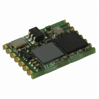
... SPBT2532C2.AT ® Bluetooth technology class-2 module Description The SPBT2532C2. micro-sized Bluetooth module, designed to ensure maximum performance in a minimum space. It includes all the functions, and only those, required for a wireless modem. Even the pin count is optimized, including supply input, UART and 4 GPIOs for AT command communication ...
Page 2
... Pin description . . . . . . . . . . . . . . . . . . . . . . . . . . . . . . . . . . . . . . . . . . . . . 13 7 Software architecture . . . . . . . . . . . . . . . . . . . . . . . . . . . . . . . . . . . . . . . 14 8 Hardware design . . . . . . . . . . . . . . . . . . . . . . . . . . . . . . . . . . . . . . . . . . . 15 8.1 Component drawing . . . . . . . . . . . . . . . . . . . . . . . . . . . . . . . . . . . . . . . . . 15 8.2 UART interface . . . . . . . . . . . . . . . . . . . . . . . . . . . . . . . . . . . . . . . . . . . . . 16 8.3 Typical circuit . . . . . . . . . . . . . . . . . . . . . . . . . . . . . . . . . . . . . . . . . . . . . . 16 8.4 Reset function . . . . . . . . . . . . . . . . . . . . . . . . . . . . . . . . . . . . . . . . . . . . . 17 9 Application information . . . . . . . . . . . . . . . . . . . . . . . . . . . . . . . . . . . . . 18 9.1 Antenna choice . . . . . . . . . . . . . . . . . . . . . . . . . . . . . . . . . . . . . . . . . . . . 19 9.2 Antenna coupling . . . . . . . . . . . . . . . . . . . . . . . . . . . . . . . . . . . . . . . . . . . 20 9.3 Example of trace calculation . . . . . . . . . . . . . . . . . . . . . . . . . . . . . . . . . . 20 10 Soldering . . . . . . . . . . . . . . . . . . . . . . . . . . . . . . . . . . . . . . . . . . . . . . . . . 21 2/50 Doc ID 16089 Rev 7 SPBT2532C2.AT ...
Page 3
... SPBT2532C2.AT Appendix A Certifications . . . . . . . . . . . . . . . . . . . . . . . . . . . . . . . . . . . . . . . . . . . 22 A.1 FCC compliance . . . . . . . . . . . . . . . . . . . . . . . . . . . . . . . . . . . . . . . . . . . . 22 A.2 CE certification . . . . . . . . . . . . . . . . . . . . . . . . . . . . . . . . . . . . . . . . . . . . . 22 A.3 BQB certification . . . . . . . . . . . . . . . . . . . . . . . . . . . . . . . . . . . . . . . . . . . . 22 Appendix B.1 Purpose B.2 Definitions and acronyms . . . . . . . . . . . . . . . . . . . . . . . . . . . . . . . . . . . . . 23 B.3 abSerial interface overview . . . . . . . . . . . . . . . . . . . . . . . . . . . . . . . . . . . . 24 B.4 Factory defaults . . . . . . . . . . . . . . . . . . . . . . . . . . . . . . . . . . . . . . . . . . . . . 24 Appendix C Commands list . . . . . . . . . . . . . . . . . . . . . . . . . . . . . . . . . . . . . . . . . . 25 Appendix D Command description . . . . . . . . . . . . . . . . . . . . . . . . . . . . . . . . . . . . 27 D.1 Bond . . . . . . . . . . . . . . . . . . . . . . . . . . . . . . . . . . . . . . . . . . . . . . . . . . . . . 27 D.1.1 D.1.2 D.2 BtcVersion . . . . . . . . . . . . . . . . . . . . . . . . . . . . . . . . . . . . . . . . . . . . . . . . . 27 D.2.1 D.3 Build . . . . . . . . . . . . . . . . . . . . . . . . . . . . . . . . . . . . . . . . . . . . . . . . . . . . . 27 D.3.1 D ...
Page 4
... D.17.2 D.18 HostEvent . . . . . . . . . . . . . . . . . . . . . . . . . . . . . . . . . . . . . . . . . . . . . . . . . 35 D.18.1 D.18.2 D.19 LinkDisconnect . . . . . . . . . . . . . . . . . . . . . . . . . . . . . . . . . . . . . . . . . . . . . 35 D.19.1 D.19.2 D.20 LocalName . . . . . . . . . . . . . . . . . . . . . . . . . . . . . . . . . . . . . . . . . . . . . . . . 35 D.20.1 4/50 Responses . . . . . . . . . . . . . . . . . . . . . . . . . . . . . . . . . . . . . . . . . . . . . . . 30 Syntax Responses . . . . . . . . . . . . . . . . . . . . . . . . . . . . . . . . . . . . . . . . . . . . . . . 31 Syntax Responses . . . . . . . . . . . . . . . . . . . . . . . . . . . . . . . . . . . . . . . . . . . . . . . 31 Syntax Responses . . . . . . . . . . . . . . . . . . . . . . . . . . . . . . . . . . . . . . . . . . . . . . . 31 Syntax Responses . . . . . . . . . . . . . . . . . . . . . . . . . . . . . . . . . . . . . . . . . . . . . . . 33 Syntax Responses . . . . . . . . . . . . . . . . . . . . . . . . . . . . . . . . . . . . . . . . . . . . . . . 33 Syntax Responses . . . . . . . . . . . . . . . . . . . . . . . . . . . . . . . . . . . . . . . . . . . . . . . 33 Syntax Responses . . . . . . . . . . . . . . . . . . . . . . . . . . . . . . . . . . . . . . . . . . . . . . . 34 Syntax Responses . . . . . . . . . . . . . . . . . . . . . . . . . . . . . . . . . . . . . . . . . . . . . . . 34 Syntax Responses . . . . . . . . . . . . . . . . . . . . . . . . . . . . . . . . . . . . . . . . . . . . . . . 34 Syntax Responses . . . . . . . . . . . . . . . . . . . . . . . . . . . . . . . . . . . . . . . . . . . . . . . 35 Syntax Responses . . . . . . . . . . . . . . . . . . . . . . . . . . . . . . . . . . . . . . . . . . . . . . . 35 Syntax Doc ID 16089 Rev 7 SPBT2532C2.AT ...
Page 5
... SPBT2532C2.AT D.20.2 D.21 PortDisconnect . . . . . . . . . . . . . . . . . . . . . . . . . . . . . . . . . . . . . . . . . . . . . 36 D.21.1 D.21.2 D.22 Reset . . . . . . . . . . . . . . . . . . . . . . . . . . . . . . . . . . . . . . . . . . . . . . . . . . . . . 36 D.22.1 D.22.2 D.23 RoleSwitch . . . . . . . . . . . . . . . . . . . . . . . . . . . . . . . . . . . . . . . . . . . . . . . . 36 D.23.1 D.23.2 D.24 SetOrigPin D.24.1 D.24.2 D.25 SetTermPin . . . . . . . . . . . . . . . . . . . . . . . . . . . . . . . . . . . . . . . . . . . . . . . . 37 D.25.1 D.25.2 D.26 SmartCableSetup . . . . . . . . . . . . . . . . . . . . . . . . . . . . . . . . . . . . . . . . . . . 37 D.26.1 D.26.2 D.27 SPPConnect . . . . . . . . . . . . . . . . . . . . . . . . . . . . . . . . . . . . . . . . . . . . . . . 38 D.27.1 D.27.2 D.28 SPPDisconnect . . . . . . . . . . . . . . . . . . . . . . . . . . . . . . . . . . . . . . . . . . . . . 38 D.28.1 D.28.2 D.29 StreamingSerial D.29.1 D.29.2 D.29.3 D.30 UpdateInquiryScan . . . . . . . . . . . . . . . . . . . . . . . . . . . . . . . . . . . . . . . . . . 39 D ...
Page 6
... E.3 ErrFormat . . . . . . . . . . . . . . . . . . . . . . . . . . . . . . . . . . . . . . . . . . . . . . . . . 42 E.4 ErrInvalidParam E.5 ErrNumParam . . . . . . . . . . . . . . . . . . . . . . . . . . . . . . . . . . . . . . . . . . . . . . 43 E.6 ErrUnknownCmd . . . . . . . . . . . . . . . . . . . . . . . . . . . . . . . . . . . . . . . . . . . . 43 E.7 ErrInProgress . . . . . . . . . . . . . . . . . . . . . . . . . . . . . . . . . . . . . . . . . . . . . . 43 E.8 Commands and associated errors . . . . . . . . . . . . . . . . . . . . . . . . . . . . . . 44 Appendix F Other responses . . . . . . . . . . . . . . . . . . . . . . . . . . . . . . . . . . . . . . . . 46 F.1 Reset . . . . . . . . . . . . . . . . . . . . . . . . . . . . . . . . . . . . . . . . . . . . . . . . . . . . . 46 F.2 Escape sequence . . . . . . . . . . . . . . . . . . . . . . . . . . . . . . . . . . . . . . . . . . . 46 F.3 Controlled disconnect . . . . . . . . . . . . . . . . . . . . . . . . . . . . . . . . . . . . . . . . 46 F.4 Unexpected disconnect . . . . . . . . . . . . . . . . . . . . . . . . . . . . . . . . . . . . . . . 47 Ordering information scheme . . . . . . . . . . . . . . . . . . . . . . . . . . . . . . . . . . . . . . . . . 48 Revision history . . . . . . . . . . . . . . . . . . . . . . . . . . . . . . . . . . . . . . . . . . . . . . . . . . . . 49 6/50 Syntax Responses . . . . . . . . . . . . . . . . . . . . . . . . . . . . . . . . . . . . . . . . . . . . . . . 40 Doc ID 16089 Rev 7 SPBT2532C2.AT ...
Page 7
... SPBT2532C2.AT 1 RoHS compliance ST modules are RoHS compliant and being based on ST devices comply with ECOPACK norms implemented by ST. 2 Application ● Serial cable replacement ● Industrial control ● Data acquisition equipment ● Machine control ● Sensor monitoring ● Security control Doc ID 16089 Rev 7 RoHS compliance ® ...
Page 8
... Block diagram 3 Block diagram Figure 1. Block diagram 8/50 Doc ID 16089 Rev 7 SPBT2532C2.AT ...
Page 9
... SPBT2532C2.AT 4 Electrical characteristics 4.1 Absolute maximum ratings Table 1. Absolute maximum ratings Storage temperature range Supply voltage input power Input voltage tolerant pin Input voltage on non-5 V tolerant pin 4.2 Operating ranges Operating ranges define the limits for functional operation and parametric characteristics of the module ...
Page 10
... R Pull-up resistor PU R Pull-down resistor PD 10/50 Modes Parameter Conditions V = 3.0 V (pin 3.0 V (pin 3.0 V (pin 3.0 V (pin 0 2 Resistor turned on Resistor turned on Doc ID 16089 Rev 7 SPBT2532C2.AT Avg Unit 41.0 mA 41.0 mA 28.9 mA 34.5 mA 28.0 mA 3.1 mA Min Max Unit - 0.9 2 0 4.0 ...
Page 11
... SPBT2532C2.AT 5 Bluetooth parameters 5.1 RF performance characteristics In the performance characteristics table the following applies: ● Test condition: nominal ● Voltage: typical, V ● Temperature: typical T Table 5. RF performance characteristics Parameters Antenna load Radio receiver Sensitivity level Maximum usable level Input VSWR Radio transmitter ...
Page 12
... Pin settings 6 Pin settings 6.1 Pin connections Pin connection diagram Figure 2. 12/50 Doc ID 16089 Rev 7 SPBT2532C2.AT 10.50 ...
Page 13
... SPBT2532C2.AT 6.2 Pin description Table 6. Pin description Pin n° Name UART interface 13 RXD 14 TXD 11 CTS 12 RTS Antenna 6 ANT Reserved 9 Reserved Power and ground GND Reset 10 RESETN GPIO – general purpose input/output 1 GPIO [1] 2 GPIO [2] 3 GPIO [3] 4 GPIO [4] 1. ADC pin functions are not 5V tolerant, when used as ALT pin function. Otherwise the I/O pins are all 5V tolerant ...
Page 14
... Software architecture 7 Software architecture The SPBT2532C2.AT includes the Bluetooth full protocol stack with upper layers and profiles. Figure 3. Bluetooth firmware implementation 14/50 Doc ID 16089 Rev 7 SPBT2532C2.AT ...
Page 15
... SPBT2532C2.AT 8 Hardware design Notes: ● All unused pins should be left floating; do not ground. ● All GND pins must be well grounded. ● Traces should not be routed underneath the module. 8.1 Component drawing Figure 4. Pin placement Figure 5. Ground plane diagram Doc ID 16089 Rev 7 ...
Page 16
... Four signals are provided with the UART interface. The TXD and RXD pins are used for data while the CTS and RTS pins are used for flow control. Figure 6. Connection to host device 8.3 Typical circuit Figure 7. Typical RS232 circuit 16/50 Doc ID 16089 Rev 7 SPBT2532C2.AT ...
Page 17
... SPBT2532C2.AT 8.4 Reset function Module reset is simply performed by forcing at low level pin 10. Reset can be operated manually or via host. Manually reset: Pin 10 is driven by a simple push button. Host controlled reset: Pin 10 is driven by an host I/O port. Reset pin can be also left open; in this case the reset function will be performed at each module power on ...
Page 18
... Keep the RF ground separate from the module supply voltage ground; the two grounds are already connected inside the module in one point, see below a possible implementation. Figure 9. Example of antenna integration on the STEVAL-SPBT2ATV2 18/50 Module foot print Doc ID 16089 Rev 7 SPBT2532C2.AT Antenna ...
Page 19
... SPBT2532C2.AT 9.1 Antenna choice RF output pin must be connected to an antenna which could be: ● Antenna directly printed on the PCB ● Integrated SMD antenna, including but not limited to following examples – Johanson Technology 2450T18A100S – Antenova 30-30-A5839-01 – Murata ANCV12G44SAA127 – Pulse W3008 – ...
Page 20
... Cu thickness of 41 µm, the strip-line width must be 1.9 mm (Micro strip type calculation). Tools for calculating the characteristic impedance, based on the physical and mechanical characteristics of the PCB, can be easily found on the web. Figure 13. Parameters for trace matching 20/50 Doc ID 16089 Rev 7 SPBT2532C2.AT ε ε 4.3 at 2.4 GHz, ...
Page 21
... SPBT2532C2.AT 10 Soldering Soldering phase has to be executed with care: In order to avoid undesired melting phenomenon, particular attention has to be taken on the set up of the peak temperature. Here following some suggestions for the temperature profile based on IPC/JEDEC J-STD-020C, July 2004 recommendations. Table 7. Soldering ...
Page 22
... FCC compliance FCC qualification is strictly related to RF section design; therefore it doesn’t apply to the module without antenna on board. However, the SPBT2532C2.AT module even if not formally qualified, is FCC compliant. In fact sub-set of the qualified module with antenna, SPBT2532C2A.AT; FCC ID X3ZBTMOD2. The list of the tests needed for final compliance and certification for the target application must be verified with the certification body ...
Page 23
... SPBT2532C2.AT Appendix B Appendix B gives a basic overview of the abSerial v1.2 FW, a third party IP developed by Amp'edeRF. AbSerial, a simple set of AT commands, provides an easy to use interface for module configuration and for usage of serial cable replacement service built on top of Bluetooth serial port profile. Figure 15. SW developer B ...
Page 24
... Service name: “AMP-SPP” ● Deep sleep: disabled ● Page and inquiry scan: 1.28 s interval duration ● Security: disabled ● Bonding PIN: “1234” ● Bonding allowed: always enabled 24/50 Bluetooth Device AT Cmds Doc ID 16089 Rev 7 SPBT2532C2.AT Bluetooth Device ...
Page 25
... SPBT2532C2.AT Appendix C Commands list This chapter details the each of the abSerial AT commands including brief descriptions of behavior, syntax of the command, context of the command, and types of responses. This abSerial reference guide covers the following commands: Table Key: √ – command is supported in this release Table 9 ...
Page 26
... SetTermPin SmartCableSetup SPPConnect SPPDisconnect StreamingSerial UpdateInquiryScan UpdatePageScan Version Power Mode feature commands. now under assessment will be fully supported by next abSerial release. For more details about abSerial command contact us at onlinesupport@st.com 26/50 Command Doc ID 16089 Rev 7 SPBT2532C2.AT abSerial v1.2 ...
Page 27
... SPBT2532C2.AT Appendix D Command description The following subsections describe each of these commands in detail, including a description of behavior, syntax (including possible parameter values), and types of responses. Some responses will not be “immediate”. Where applicable, these will be noted and will include an approximate delay before response. ...
Page 28
... ChangeBaud The host sends the ChangeBaud command in order to change the local UART speed to a new speed identified by the host. This setting will only remain in effect during the current session - until reset. D.5.1 Syntax AT+AB ChangeBaud [rate] 28/50 Doc ID 16089 Rev 7 SPBT2532C2.AT ...
Page 29
... SPBT2532C2.AT where [rate] is the new baud rate: ● 1200 ● 2400 ● 4800 ● 9600 ● 19,200 ● 38,400 ● 57,600 ● 115,200 ● 230,400 ● 460,800 ● 921,600 D.5.2 Responses If the change is accepted, the response is: AT-AB Baudrate Changed The actual change will not occur until the response has been completely transmitted. ...
Page 30
... Suggested GPIO to use are setting of none means that this function is disabled GPIO register used to wake up the module after it enters deep sleep mode. Suggested GPIO to use are setting of none means that this function is disabled Doc ID 16089 Rev 7 SPBT2532C2.AT Description ...
Page 31
... SPBT2532C2.AT D.9 DeleteSmartCable The DeleteSmartCable command removes the current Smart Cable settings that were entered using the SmartCableSetup command, but not the setting from the dynamic configuration. The Smart Cable will then be deactivated for the remainder of this session. Upon reset dynamic configuration for a Smart Cable exists, it will be activated. If there is no dynamic configuration Smart Cable setup, then this feature will remain deactivated ...
Page 32
... AT+AB EnableBond [BD addr] [PIN] AT+AB EnableBond [BD addr] [PIN] [timeout] Where [BD addr] is the BD Address of the remote device with which to bond, [PIN] is the PIN code to use ( characters), and [timeout] is the duration of the timeout in seconds (1 to 1000, in decimal). 32/50 [BD addr] "Unknown" Doc ID 16089 Rev 7 SPBT2532C2.AT ...
Page 33
... SPBT2532C2.AT D.12.2 Responses If the operation is successful, the response is: AT-AB BondEnabled If bonding has been initiated by a remote device, the notification is: AT-AB BondPending [BD addr] where [BD addr] is the BD address of the remote device that initiated the bonding. If bonding has occurred, the notification is: AT-AB BondOk [BD addr] where [BD addr] is the BD address of the remote device with successful bonding ...
Page 34
... D.17.1 Syntax AT+AB GPIOWrite [GPIO Pin] [Setting] Where [GPIO Pin] is the Pin number, 1 – the desired GPIO to read. [Setting set a pin to high and set a pin to low. D.17.2 Responses If the operation is successful, the response is: AT-AB GPIOWriteDone 34/50 Doc ID 16089 Rev 7 SPBT2532C2.AT ...
Page 35
... SPBT2532C2.AT D.18 HostEvent The HostEvent command is used to enable/disable the host notification strings. This will override the default setting in the dynamic configuration only for the current session; until reset. D.18.1 Syntax AT+AB HostEvent [Enable/Disable] Where [Enable/Disable character to enable this parameter and character to disable it. ...
Page 36
... The RoleSwitch command is used to change a link from/to a Master or Slave role D.23.1 Syntax AT+AB RoleSwitch [BD address] [role] Where [Bd address] is the address of the remote device that will receive the role switch [role] is the new role of the local device Master Slave. 36/50 Doc ID 16089 Rev 7 SPBT2532C2.AT ...
Page 37
... SPBT2532C2.AT D.23.2 Responses If the operation is successful, the response is: AT-AB [MasterRole or SlaveRole] D.24 SetOrigPin The SetOrigPin command is used to set the PIN code used to originate a pairing to a remote device. D.24.1 Syntax AT+AB SetOrigPin [PIN] where [PIN] is the pairing code characters (case sensitive) D.24.2 Responses There is no response for this command ...
Page 38
... AT-AB ConnectionUp AT-AB -BypassMode- If the connection cannot be completed, the response is: AT-AB SPPConnectionClosed D.28 SPPDisconnect The SPPDisconnect command is used to terminate a connection with the remote device. D.28.1 Syntax AT+AB SPPDisconnect D.28.2 Responses If the connection is successful, the response is AT-AB SPPConnectionClosed 38/50 Doc ID 16089 Rev 7 SPBT2532C2.AT ...
Page 39
... SPBT2532C2.AT D.29 StreamingSerial The StreamingSerial command is used to enable/disable the UART flow control. D.29.1 Syntax AT+AB StreamingSerial [Enable/Disable] Where [Enable/Disable character to enable this parameter and character to disable it. StreamingSerial command will disable RTS/CTS hardware flow control and discard non-transmitted data when enabled. RTS/CTS flow control is enabled, when StreamingSerial is disabled ...
Page 40
... AT-AB PageScanUpdateDone D.32 Version The Version command is used to return the current version of the abSerial interface. D.32.1 Syntax AT+AB Version D.32.2 Responses If the operation is successful, the response is: AT-AB abSerialVer [x.y] where [x.y] is the current version of the abSerial Interface. 40/50 Doc ID 16089 Rev 7 SPBT2532C2.AT ...
Page 41
... SPBT2532C2.AT Appendix E Error responses Appendix E details the error responses that occur under specific circumstances. There are seven error responses that can occur beyond error responses specific to a particular command (e.g., Discovery). They are: ● ErrConnect ● ErrExecution ● ErrFormat ● ErrInvalidParam ● ...
Page 42
... Unrecognized (or unsupported) symbolic AT-AB ErrInvalidParam goep parameter used. Numeric parameter is out of range (specified AT-AB ErrInvalidParam 1600 baud rate is not supported by command). AT-AB ErrInvalidParam String parameter (PIN)has too many 12345678901234567 characters. Doc ID 16089 Rev 7 SPBT2532C2.AT Reason Reason ...
Page 43
... SPBT2532C2.AT E.5 ErrNumParam The ErrNumParam error response will be sent if there are too few parameters for the requested command. A command sent with too many parameters does not generate an error; instead, the extra parameters are ignored. Warning: Examples of commands that produce this error response are given in the following table. ...
Page 44
... Possible ErrConnect error responses Command ErrInvalidParam Bond BtcVersion Build Bypass ChangeBaud ChangeDefaultBaud Config DefaultLocalName DeleteSmartCable DisableBond Discovery EnableBond EraseBondTable GetBdAddress GPIOConfig GPIORead GPIOWrite HostEvent LinkDisconnect LocalName PortDisconnect Reset RoleSwitch SetOrigPin SetTermPin SmartCableSetup SPPConnect SPPDisconnect StreamingSerial 44/50 ErrNumParam ErrExecute Doc ID 16089 Rev 7 SPBT2532C2.AT ErrConnect ErrInProgress ...
Page 45
... SPBT2532C2.AT Table 17. Possible ErrConnect error responses (continued) Command ErrInvalidParam UpdateInquiryScan UpdatePageScan Version ErrNumParam ErrExecute Doc ID 16089 Rev 7 Error responses ErrConnect ErrInProgress X X 45/50 ...
Page 46
... F.3 Controlled disconnect If the local host initiates a disconnect, it must first put the abSerial interface into command mode (see the section on Escape Sequence directly above). After a successful disconnect command, the following response is made: AT-AB ConnectionDown 46/50 Doc ID 16089 Rev 7 SPBT2532C2.AT ...
Page 47
... SPBT2532C2.AT F.4 Unexpected disconnect Bluetooth connections may be unexpectedly dropped (e.g., in changing RF conditions). Although it is generally assumed that a disconnect will be negotiated on the application level, the remote device may initiate a disconnect. When that happens, the disconnect may be unexpected. This section applies to both the general case and the unexpected disconnect useful for the local host to be notified that a connection has been terminated when it isn’ ...
Page 48
... Ordering information scheme Ordering information scheme Table 18. Ordering information scheme ® Bluetooth modules V2.1 compliant Class 2 AT command set Note: No antenna on board 48/50 SPBT 2532 Doc ID 16089 Rev 7 SPBT2532C2.AT C2 .AT ...
Page 49
... SPBT2532C2.AT Revision history Table 19. Document revision history Date 07-Aug-2009 04-Nov-2009 24-Feb-2010 01-Jul-2010 27-Sep-2010 03-Jan-2011 13-Apr-2011 Revision 1 First release Updated Figure 1, Table 2 Chapter Appendix B 3 Updated Chapter 4, Added Section 9 on page 4 Updated Appendix 5 Updated Coverpage and Updated Coverpage, 6 Chapter 8.2, Figure Appendix D ...
Page 50
... Australia - Belgium - Brazil - Canada - China - Czech Republic - Finland - France - Germany - Hong Kong - India - Israel - Italy - Japan - Malaysia - Malta - Morocco - Philippines - Singapore - Spain - Sweden - Switzerland - United Kingdom - United States of America 50/50 Please Read Carefully: © 2011 STMicroelectronics - All rights reserved STMicroelectronics group of companies www.st.com Doc ID 16089 Rev 7 SPBT2532C2.AT ...