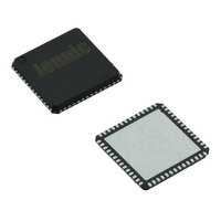
JN5148-001-X NXP Semiconductors, JN5148-001-X Datasheet - Page 56

JN5148-001-X
Manufacturer Part Number
JN5148-001-X
Description
IC MCU 802.15.4 32BIT 2.4G 56QFN
Manufacturer
NXP Semiconductors
Series
JN5148r
Datasheet
1.JN5148-UG010.pdf
(99 pages)
Specifications of JN5148-001-X
Frequency
2.4GHz
Data Rate - Maximum
667kbps
Modulation Or Protocol
802.15.4
Applications
Home/Building Automation, Industrial Control
Power - Output
2.5dBm
Sensitivity
-95dBm
Voltage - Supply
2 V ~ 3.6 V
Current - Receiving
17.5mA
Current - Transmitting
15mA
Data Interface
PCB, Surface Mount
Memory Size
128kB RAM, 128kB ROM
Antenna Connector
PCB, Surface Mount
Operating Temperature
-40°C ~ 85°C
Package / Case
56-QFN
Lead Free Status / RoHS Status
Lead free / RoHS Compliant
Other names
616-1049-2
935293999531
JN5148-001-X
935293999531
JN5148-001-X
If data is queued for transmission and the recipient has indicated that they are ready for it (RXRDY in incoming status
byte was 1), the next byte to be transmitted is the data length in words (N). If either the JN5148 or the remote
processor has no data to transfer, then the data length should be set to zero. The transaction can be terminated by
the master after the status and padding bytes have been sent if it is not possible to send data in either direction. This
may be because neither party has data to send or because the receiver does not have a buffer available. If the data
length is non-zero, the data in the JN5148 transmit memory buffer is sent, beginning at the start of the buffer. At the
same time that data bytes are being sent from the transmit buffer, the JN5148 receive buffer is being filled with
incoming data, beginning from the start of the buffer.
The remote processor, acting as the master, must determine the larger of its incoming or outgoing data transfers and
deassert IP_SEL when all of the transmit and receive data has been transferred. The data is transferred into or out of
the buffers starting from the lowest address in the buffer, and each word is assembled with the MSB first on the serial
data lines. Following a transaction, IP_SEL must be high (deasserted) for at least 400nsec before a further
transaction can begin.
IP_SEL
IP_CLK
padding (8-bit)
N words of data
IP_DI
data length or 0s (8-bit)
Status (8-bit)
IP_DO
N words of data
padding (8-bit)
Status (8-bit)
data length or 0s (8-bit)
Figure 42: Intelligent Peripheral Data Transfer Waveforms
The N words of data transferred on the interface are also formatted. The first three bytes, of the first word, must be
zero. These are followed by a one byte length field that must be one less than the data length shown in the data
length field in Figure 42, i.e. N-1. Following this are the (N-1) words of data.
The application running on the JN5148 has high level software functions for sending and receiving data on this
interface. The function of generating and interpreting the individual bytes on the interface is handled by hardware
within the device. The remote processor must generate, and interpret, the signals in the interface. For instance, this
may be done with a configurable SPI master interface.
19.2 JN5148 (Slave) Initiated Data Transfer
To send data, the data is written into either buffer 0 or 1 of the intelligent peripheral memory area. Then the buffer
number is written together with the data length. If the call is successful, the interrupt line IP_INT will signal to the
remote processor that there is a message ready to be sent from the JN5148. When a remote processor starts a
transfer to the JN5148 by deasserting IP_SEL, then IP_INT is deasserted. If the transfer is unsuccessful and the
data is not output then IP_INT is reasserted after the transfer to indicate that data is still waiting to be sent.
The interface can be configured to generate an internal interrupt whenever a transaction completes (for example
IP_SEL becomes inactive after a transfer starts). It is also possible to mask the interrupt. The end of the
transmission can be signalled by an interrupt, or the interface can be polled.
To receive data the interface must be firstly initialised and when this is done, the bit RXRDY sent in the status byte
from the IP block will show that data can be received by the JN5148. Successful data arrival can be indicated by an
interrupt, or the interface can be polled. IP_INT is asserted if the JN5148 is configured to be able to receive, and the
remote processor has previously attempted to send data but the RXRDY indicated that it could not be sent.
To send and receive at the same time, the transmit and receive buffers must be set to be different.
19.3 Remote (Master) Processor Initiated Data Transfer
The remote processor (master) must initiate a transfer to send data to the JN5148 (slave) by asserting the slave
select pin, IP_SEL, and generating its status byte on IP_DI with TXRDY set. After receiving the status byte from the
JN5148, the master should check that the JN5148 has a buffer ready by reading the RXRDY bit of the received
status byte. If the RXRDY bit is 0 indicating that the JN5148 cannot accept data, it must terminate the transfer by
deasserting IP_SEL unless it is receiving data from the JN5148. If the RXRDY bit is 1, indicating that the JN5148 can
accept data, then the master should generate a further 8 clocks on IP_CLK in order to transfer its own message
length on IP_DI. The master must continue clocking the interface until sufficient clocks have been generated to send
56
JN-DS-JN5148-001 1v6
© NXP Laboratories UK 2010


