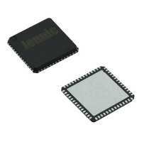
JN5148-001-X NXP Semiconductors, JN5148-001-X Datasheet - Page 51

JN5148-001-X
Manufacturer Part Number
JN5148-001-X
Description
IC MCU 802.15.4 32BIT 2.4G 56QFN
Manufacturer
NXP Semiconductors
Series
JN5148r
Datasheet
1.JN5148-UG010.pdf
(99 pages)
Specifications of JN5148-001-X
Frequency
2.4GHz
Data Rate - Maximum
667kbps
Modulation Or Protocol
802.15.4
Applications
Home/Building Automation, Industrial Control
Power - Output
2.5dBm
Sensitivity
-95dBm
Voltage - Supply
2 V ~ 3.6 V
Current - Receiving
17.5mA
Current - Transmitting
15mA
Data Interface
PCB, Surface Mount
Memory Size
128kB RAM, 128kB ROM
Antenna Connector
PCB, Surface Mount
Operating Temperature
-40°C ~ 85°C
Package / Case
56-QFN
Lead Free Status / RoHS Status
Lead free / RoHS Compliant
Other names
616-1049-2
935293999531
JN5148-001-X
935293999531
JN5148-001-X
16 Four-Wire Digital Audio Interface
The JN5148 includes a four-wire digital audio interface that can be used for interfacing to audio CODECs. The
following features are supported:
The Word Select (WS), Data In (SDIN), Clock (SCK) and Data Out (SDOUT) lines are alternate functions of DIO
lines 12,13,17 and 18 respectively.
Data transfer is always bidirectional. Data placed in the Data Buffer before a transfer command is issued will be
transmitted on SDOUT whilst the data received on SDIN will be placed in the Data Buffer at the end of the transfer.
Indication that a transfer has completed is by means of an interrupt or by polling a status bit.
Left channel data is always sent first, with MSB first on each channel. The interface will always transfer both left and
right channel data. For mono data transfer, the user should pad out the unused channel with 0’s, and ignore any data
returned on the unused channel.
The length of a data transfer is derived as follows:
Timing of the 3 main modes is shown in Figure 38, Figure 39 and Figure 40. The Data Buffer shows how the data is
stored and how it will be transferred onto the interface. SD Max Size indicates how the maximum transfer size (16
with no additional padding) will transfer, whilst SD 3-bits indicates how 3 bits of data will be aligned when padding is
enabled. Received data in the Data Buffer will always be padded out with 0’s if the Data Transfer Size is less than 16-
bits, and any bits received beyond 16-bits when extra padding is used, will be discarded. In the examples, the polarity
of WS is shown with Left channel = 0, and the idle state is Right Channel.
© NXP Laboratories UK 2010
•
•
•
•
•
•
•
•
•
•
•
•
•
•
•
Compatible with the industry standard I²S interface
Option to support I²S, left justified and right justified modes
Optional support for connection to mono sample FIFO with data transferred on the left or right channel
Master only
Transmit on falling edge and receive on rising edge
Up to 8MHz maximum clock range
Maximum system size of 32-bits, allowing up to 16-bits per channel (left or right channels)
Option for pad bit insertion, allowing length of transfer per channel to be anything from 16 to 32 bits
Data Transfer size range of 1 to 16-bits per channel
Option to invert WS (normally 0 for left, but allow 1 for left instead)
Continuous clock output option to support CODECs which use it as a clock source
Separate input and output data lines
Option to invert idle state of WS (to indicate left or right)
When padding is disabled – Data Transfer Length = 2 x Data Transfer Size
When padding is enabled – Data Transfer Length = 2 x (16 + Extra Pad Length)
JN-DS-JN5148-001 1v6
51


