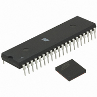
ATMEGA64RZAV-10PU Atmel, ATMEGA64RZAV-10PU Datasheet - Page 61

ATMEGA64RZAV-10PU
Manufacturer Part Number
ATMEGA64RZAV-10PU
Description
MCU ATMEGA644/AT86RF230 40-DIP
Manufacturer
Atmel
Series
ATMEGAr
Datasheets
1.ATMEGA644-20MU.pdf
(23 pages)
2.ATMEGA644-20MU.pdf
(376 pages)
3.AT86RF230-ZU.pdf
(98 pages)
Specifications of ATMEGA64RZAV-10PU
Frequency
2.4GHz
Modulation Or Protocol
802.15.4 Zigbee
Power - Output
3dBm
Sensitivity
-101dBm
Voltage - Supply
1.8 V ~ 3.6 V
Data Interface
PCB, Surface Mount
Memory Size
64kB Flash, 2kB EEPROM, 4kB RAM
Antenna Connector
PCB, Surface Mount
Package / Case
40-DIP (0.600", 15.24mm)
Wireless Frequency
2.4 GHz
Interface Type
JTAG, SPI
Output Power
3 dBm
For Use With
ATSTK600-TQFP32 - STK600 SOCKET/ADAPTER 32-TQFPATAVRISP2 - PROGRAMMER AVR IN SYSTEMATSTK500 - PROGRAMMER AVR STARTER KIT
Lead Free Status / RoHS Status
Lead free / RoHS Compliant
Operating Temperature
-
Applications
-
Data Rate - Maximum
-
Current - Transmitting
-
Current - Receiving
-
Lead Free Status / Rohs Status
Lead free / RoHS Compliant
For Use With/related Products
ATmega64
Figure 9-1. Frame Structure
9.3.3 Frame Buffer Interrupt Handling
5131E-MCU Wireless-02/09
A frame comprises two sections, the fixed internally generated SHR field and the user
accessible part stored in the Frame Buffer. The first fixed part of the frame consists of
the preamble and the SFD field. The variable frame section contains the frame length
field and the frame payload followed by the FCS field. The Frame Buffer content differs
depending on the direction of the communication (RX or TX). To access the data follow
the procedures described in sections 6.2.2 and 6.2.3.
In any of the receive states, the payload and the link quality indicator (LQI) value of a
successfully received frame are stored to the Frame Buffer. The radio transceiver
appends the LQI value to the PSDU data. The frame length information is not stored to
the Frame Buffer. When using the Frame Buffer access mode to read the Frame Buffer
content, the PHR octet is automatically prefixed to the payload during the upload
process. If the SRAM access mode is used, the frame length information cannot be
accessed. The preamble or the SFD value cannot be read.
For frame transmission, the PHR octet and the PSDU data shall be stored to the Frame
Buffer. If the TX_AUTO_CRC_ON bit is set in register 0x05 (PHY_TX_PWR), the FCS
field is replaced by the automatically calculated FCS during frame transmission. There
is no need to download the FCS field when using the automatic FCS generation.
For non IEEE 802.15.4-2003 frames, the minimum PSDU length supported by the
AT86RF230 is one byte.
Access conflicts may occur when reading or writing data simultaneously at the two
independent ports of the Frame Buffer, BBP and SPI. Both of these ports have its own
address counter that points to the Frame Buffer’s current address.
During Frame Buffer read access, if the SPI port’s address counter value is more than
or equal to that of TX/RX BBP port then an access violation occurs. This indicates that
the SPI transfer rate is higher than the PHY data rate.
Similar on Frame Buffer write access, an access violation occurs if the SPI port’s
address counter value is less than or equal to that of TX/RX BBP port. This access
violation can occur if the SPI transfer rate during a frame download is slower than the
PHY data rate, while having started the frame transmission already.
Both these access violations may cause data corruption and are indicated by TRX_UR
interrupt when using the Frame Buffer access mode. Access violations are not indicated
when using the SRAM access mode.
While receiving a frame, primarily the data needs to be stored to the Frame Buffer
before reading it. This can be ensured by starting the Frame Buffer read access 32 µs
after the RX_START interrupt at the earliest. When reading the frame data continuously
AT86RF230
61


