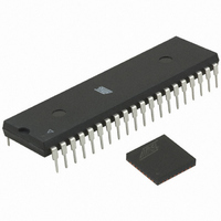
ATMEGA64RZAV-10PU Atmel, ATMEGA64RZAV-10PU Datasheet - Page 54

ATMEGA64RZAV-10PU
Manufacturer Part Number
ATMEGA64RZAV-10PU
Description
MCU ATMEGA644/AT86RF230 40-DIP
Manufacturer
Atmel
Series
ATMEGAr
Datasheets
1.ATMEGA644-20MU.pdf
(23 pages)
2.ATMEGA644-20MU.pdf
(376 pages)
3.AT86RF230-ZU.pdf
(98 pages)
Specifications of ATMEGA64RZAV-10PU
Frequency
2.4GHz
Modulation Or Protocol
802.15.4 Zigbee
Power - Output
3dBm
Sensitivity
-101dBm
Voltage - Supply
1.8 V ~ 3.6 V
Data Interface
PCB, Surface Mount
Memory Size
64kB Flash, 2kB EEPROM, 4kB RAM
Antenna Connector
PCB, Surface Mount
Package / Case
40-DIP (0.600", 15.24mm)
Wireless Frequency
2.4 GHz
Interface Type
JTAG, SPI
Output Power
3 dBm
For Use With
ATSTK600-TQFP32 - STK600 SOCKET/ADAPTER 32-TQFPATAVRISP2 - PROGRAMMER AVR IN SYSTEMATSTK500 - PROGRAMMER AVR STARTER KIT
Lead Free Status / RoHS Status
Lead free / RoHS Compliant
Operating Temperature
-
Applications
-
Data Rate - Maximum
-
Current - Transmitting
-
Current - Receiving
-
Lead Free Status / Rohs Status
Lead free / RoHS Compliant
For Use With/related Products
ATmega64
8.5.3 Data Interpretation
8.6 Clear Channel Assessment (CCA)
8.6.1 Overview
54
AT86RF230
information can be read as an extra byte from the Frame Buffer (see section 9.1). The
LQI byte can be uploaded after the TRX_END interrupt.
A low LQI value is associated with low signal strength and/or high signal distortions.
Signal distortions are mainly caused by interference signals and/or multipath
propagation. High LQI values indicate a sufficient high signal power and low signal
distortions.
Note, the received signal power as indicated by received signal strength indication
(RSSI) value or energy detection (ED) value do not characterize the signal quality and
the ability to decode a signal. As an example, a received signal with an input power of
about 6 dB above the receiver sensitivity likely results in a LQI value close to 255 for
radio channels with very low signal distortions. For higher signal power levels the LQI
value becomes independent of the actual signal strength. This is because the packet
error rate for these scenarios tends towards zero and further increase of the signal
strength, i.e. by increasing the transmission power, does not decrease the error rate
any further. In this case RSSI or ED can be used to evaluate the signal strength and the
link margin.
ZigBee networks require to determine the “best” route between two nodes. Both, the
LQI and the RSSI/ED can be used for this, depending on the optimization criteria. As a
rule of thumb RSSI/ED is useful to differentiate between links with high LQI values.
Transmission links with low LQI values should be discarded for routing decisions even if
the RSSI/ED values are high.
The main features of the Clear Channel Assessment (CCA) module are:
• All 3 modes available as defined by IEEE 802.15.4-2003 in section 6.7.9
• Adjustable threshold of the energy detection algorithm
The CCA is used to detect a clear channel. There are three modes available as defined
in Table 8-4.
Table 8-4. Available CCA Modes
CCA Mode
1
2
3
Description
Energy above threshold.
CCA shall report a busy medium upon detecting any energy above the ED
threshold.
Carrier sense only.
CCA shall report a busy medium only upon the detection of a signal with the
modulation and spreading characteristics of IEEE 802.15.4. This signal may be
above or below the ED threshold.
Carrier sense with energy above threshold.
CCA shall report a busy medium only upon the detection of a signal with the
modulation and spreading characteristics of IEEE 802.15.4 with energy above
the ED threshold.
5131E-MCU Wireless-02/09


