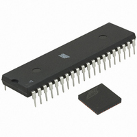
ATMEGA64RZAV-10PU Atmel, ATMEGA64RZAV-10PU Datasheet - Page 60

ATMEGA64RZAV-10PU
Manufacturer Part Number
ATMEGA64RZAV-10PU
Description
MCU ATMEGA644/AT86RF230 40-DIP
Manufacturer
Atmel
Series
ATMEGAr
Datasheets
1.ATMEGA644-20MU.pdf
(23 pages)
2.ATMEGA644-20MU.pdf
(376 pages)
3.AT86RF230-ZU.pdf
(98 pages)
Specifications of ATMEGA64RZAV-10PU
Frequency
2.4GHz
Modulation Or Protocol
802.15.4 Zigbee
Power - Output
3dBm
Sensitivity
-101dBm
Voltage - Supply
1.8 V ~ 3.6 V
Data Interface
PCB, Surface Mount
Memory Size
64kB Flash, 2kB EEPROM, 4kB RAM
Antenna Connector
PCB, Surface Mount
Package / Case
40-DIP (0.600", 15.24mm)
Wireless Frequency
2.4 GHz
Interface Type
JTAG, SPI
Output Power
3 dBm
For Use With
ATSTK600-TQFP32 - STK600 SOCKET/ADAPTER 32-TQFPATAVRISP2 - PROGRAMMER AVR IN SYSTEMATSTK500 - PROGRAMMER AVR STARTER KIT
Lead Free Status / RoHS Status
Lead free / RoHS Compliant
Operating Temperature
-
Applications
-
Data Rate - Maximum
-
Current - Transmitting
-
Current - Receiving
-
Lead Free Status / Rohs Status
Lead free / RoHS Compliant
For Use With/related Products
ATmega64
9.3 Frame Buffer
9.3.1 Frame Buffer Data Management
9.3.2 User accessible Frame Content
60
AT86RF230
The AT86RF230 contains a 128 byte dual port SRAM. One port is connected to the SPI
interface, the other to the internal TX/RX BBP port. For data communication both ports
are independent and simultaneously accessible. Access conflicts are indicated by a
TRX under run (TRX_UR) interrupt.
The Frame Buffer is used for the TX and RX operation of the device and can keep one
IEEE 802.15.4-2003 TX or one RX frame of maximum length at a time.
Note, a Frame Buffer access is only possible if the digital voltage regulator is turned on.
This is the case in all device states except in SLEEP and P_ON.
Data stored in Frame Buffer (received data or data to be transmitted) remains valid as
long as
• No new frame is written into the buffer via SPI
• No new frame is received (in any BUSY_RX state)
• No state change into SLEEP state is made
If the radio transceiver is in any RX state an incoming frame with valid SFD field
overwrites the Frame Buffer content 32 µs after the RX_START interrupt occurs, even if
the RX_START interrupt is disabled. Thus the Frame Buffer content should be
uploaded to the microcontroller before the next SFD is received. To avoid an
unintended Frame Buffer overwrite a state change to PLL_ON immediately after the
frame reception (TRX_END interrupt) is recommended.
Using the Extended Operating Mode states TX_ARET_ON or TX_ARET_ON_NOCLK,
the radio transceiver switches to RX (after successful frame transmission), if an
acknowledgement was requested in FCF. Received frames are evaluated but not
stored in the Frame Buffer in these states. This allows the radio transceiver to wait for
an acknowledgement frame and retry the data frame transmission without downloading
them again.
A radio transceiver state change, except a transition to SLEEP, does not affect the
Frame Buffer contents. If the radio transceiver is forced into SLEEP, the Frame Buffer is
powered off and the stored data gets lost.
The AT86RF230 supports an IEEE 802.15.4-2003 compliant frame format as shown in
Figure 9-1.
Register Bits
Value [3:0]
0xC
0xD
0xB
0xE
0xF
Output Power [dBm]
-12.2
-17.2
-5.2
-7.2
-9.2
5131E-MCU Wireless-02/09


