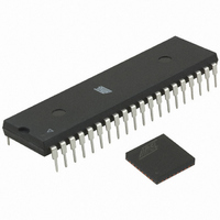
ATMEGA64RZAV-10PU Atmel, ATMEGA64RZAV-10PU Datasheet - Page 19

ATMEGA64RZAV-10PU
Manufacturer Part Number
ATMEGA64RZAV-10PU
Description
MCU ATMEGA644/AT86RF230 40-DIP
Manufacturer
Atmel
Series
ATMEGAr
Datasheets
1.ATMEGA644-20MU.pdf
(23 pages)
2.ATMEGA644-20MU.pdf
(376 pages)
3.AT86RF230-ZU.pdf
(98 pages)
Specifications of ATMEGA64RZAV-10PU
Frequency
2.4GHz
Modulation Or Protocol
802.15.4 Zigbee
Power - Output
3dBm
Sensitivity
-101dBm
Voltage - Supply
1.8 V ~ 3.6 V
Data Interface
PCB, Surface Mount
Memory Size
64kB Flash, 2kB EEPROM, 4kB RAM
Antenna Connector
PCB, Surface Mount
Package / Case
40-DIP (0.600", 15.24mm)
Wireless Frequency
2.4 GHz
Interface Type
JTAG, SPI
Output Power
3 dBm
For Use With
ATSTK600-TQFP32 - STK600 SOCKET/ADAPTER 32-TQFPATAVRISP2 - PROGRAMMER AVR IN SYSTEMATSTK500 - PROGRAMMER AVR STARTER KIT
Lead Free Status / RoHS Status
Lead free / RoHS Compliant
Operating Temperature
-
Applications
-
Data Rate - Maximum
-
Current - Transmitting
-
Current - Receiving
-
Lead Free Status / Rohs Status
Lead free / RoHS Compliant
For Use With/related Products
ATmega64
Figure 6-16. Wake-Up Initiated by Radio Transceiver Interrupt
6.5 Interrupt Logic
6.5.1 Overview
Table 6-8. Interrupt Description in Basic Operating Mode
5131E-MCU Wireless-02/09
CLKM
SLP_TR
IRQ
IRQ Name
IRQ_7: BAT_LOW
IRQ_6: TRX_UR
IRQ_3: TRX_END
IRQ_2: RX_START
IRQ_1: PLL_UNLOCK
IRQ_0: PLL_LOCK
Comments
Indicates a supply voltage below the programmed threshold.
RX:
TX:
Indicates a SFD detection. The TRX_STATE changes to BUSY_RX.
Indicates PLL unlock. The PA is turned off immediately, if the radio transceiver is in
BUSY_TX/BUSY_TX_ARET state.
Indicates PLL lock
Indicates a Frame Buffer access violation (under run).
35 main clock cycles
This can be achieved by a rising edge on pin SLP_TR which turns off the CLKM output
35 clock cycles afterwards. The radio transceiver state changes from RX_ON or
RX_AACK_ON to RX_ON_NOCLK or RX_AACK_ON_NOCLK respectively.
In case that a frame is received the radio transceiver enters the state
BUSY_RX/BUSY_RX_AACK and the clock output CLKM is automatically switched on
again. This scenario is shown in Figure 6-16.
The
RX_ON_NOCLK/RX_AACK_ON_NOCLK and state RX_ON, because only the CLKM
output is switched off.
The AT86RF230 differentiates between six interrupt events. Each interrupt is enabled
or disabled by writing the corresponding bit to the interrupt mask register 0x0E
(IRQ_MASK). Internally, each interrupt is stored as a separate bit of the interrupt status
register. All interrupt lines are combined via logical “OR” to one external interrupt line
(IRQ). If the IRQ pin issues, the microcontroller shall read the interrupt status register
0x0F (IRQ_STATUS) to determine the reason for the interrupt. A read access to this
register clears the interrupt status register and the IRQ pin, too. Interrupts are not
cleared automatically when the event that caused them is not valid anymore. Exception:
the PLL_LOCK IRQ clears the PLL_UNLOCK IRQ and vice versa. The supported
interrupts for the Basic Operating Mode (see section 7.1) are summarized in Table 6-8.
Using the Extended Operating Mode, the interrupts are handled in a slightly different
way. A detailed description can be found in section 7.2.4.
Indicates the completion of a frame reception.
Indicates the completion of a frame transmission.
power
consumption
of
the
radio
t r a n s c e iv e r IR Q is s u e d
transceiver
typ. 5µs
AT86RF230
is
similar
Details
Section 9.5.3
Section 9.3.3
Section 7.1.3
Section 7.1.3
Section 7.1.3
Section 9.7.4
Section 9.7.4
in
state
19


