DLP-USB245M-G DLP Design Inc, DLP-USB245M-G Datasheet - Page 4
DLP-USB245M-G
Manufacturer Part Number
DLP-USB245M-G
Description
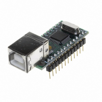
MODULE USB-TO-TTL PARL FIFO CONV
Manufacturer
DLP Design Inc
Series
DLP-USB245Mr
Datasheet
1.DLP-USB245M-G.pdf
(15 pages)
Specifications of DLP-USB245M-G
Convert From (adapter End)
USB
Convert To (adapter End)
DB9 Female
Features
Integrated 6MHz-48MHz clock multiplier PLL
Interface Type
USB
Product
Interface Modules
For Use With/related Products
Windows® 98 or higher, Mac OS 8.5 or higher
Lead Free Status / RoHS Status
Lead free / RoHS Compliant
Lead Free Status / RoHS Status
Lead free / RoHS Compliant, Lead free / RoHS Compliant
Other names
813-1019


EEPROM WRITE UTILITY
The DLP-USB245M has the option to accept manufacturer-specific information that is written into the 93C46
EEPROM. Parameters that can be programmed include the VID and the PID identifiers, the manufacturer’s product
string and a serial number.
FTD2XXST is the latest EEPROM serializer and testing utility for the FT245BM device. It replaces the VCP based
232Prog utility. FTD2XXST is based on the new D2XX drivers and will work on Win ‘98, Win ME and Win 2000/
XP platforms. You must install the latest release of the D2XX drivers in order to run this application. Refer to the
SER200.PDF guide that is included in the EEPROM Write Utility’s download zip file for details on how to use the
serializer.
If you have VCP drivers installed on the PC that is to perform the EEPROM write process you must uninstall these
drivers using the uninstaller program (included with the driver files) and install the D2XX drivers prior to running the
serializer utility.
QUICK START GUIDE
This guide requires the use of a Windows 98/2000 PC that is equipped with a USB port.
1. Download the DLL version of the device drivers from either dlpdesign.com or ftdichip.com. Unzip the drivers onto
2. Download the serializer program from either dlpdesign.com or ftdichip.com. Unzip the package and place it in a
3. Select a power source for the DLP-USB245M module via pins 10, 11, and 12. Be sure to pull the RESET# pin
4. Connect the DLP-USB245M board to the PC via a standard, 6-foot USB cable. This action initiates the loading
a blank floppy disk or into a folder on the hard drive.
folder on the hard drive.
high (pin 3).
of the USB drivers. When prompted, select the folder where the DLL version of the device drivers were stored
Copyright © DLP Design 2002
DLP-USB245M User Manual
Page 4 of 15
Related parts for DLP-USB245M-G
Image
Part Number
Description
Manufacturer
Datasheet
Request
R

Part Number:
Description:
MODULE USB-TO-UART/FIFO HS 18DIP
Manufacturer:
DLP Design Inc
Datasheet:

Part Number:
Description:
MODULE USB ADAPTER FOR FT2232D
Manufacturer:
DLP Design Inc
Datasheet:

Part Number:
Description:
MODULE USB-TO-FPGA TOOL W/MANUAL
Manufacturer:
DLP Design Inc
Datasheet:

Part Number:
Description:
Interface Modules & Development Tools RETRACTABLE USB CBL USB TO MINI USB
Manufacturer:
DLP Design Inc
Part Number:
Description:
Interface Modules & Development Tools USB FPGA Module w/ Xilinx XC3S400A
Manufacturer:
DLP Design Inc
Datasheet:

Part Number:
Description:
MODULE USB-TO-PARL FIFO 18-DIP
Manufacturer:
DLP Design Inc
Datasheet:

Part Number:
Description:
MODULE USB-TO-SRL UART 18-DIP
Manufacturer:
DLP Design Inc
Datasheet:

Part Number:
Description:
MODULE USB ADAPTR FOR FT2232D LP
Manufacturer:
DLP Design Inc
Datasheet:

Part Number:
Description:
MODULE USB-MCU FT245RL W/16F877A
Manufacturer:
DLP Design Inc
Datasheet:

Part Number:
Description:
MODULE USB-TO-FPGA TRAINING TOOL
Manufacturer:
DLP Design Inc
Datasheet:

Part Number:
Description:
MODULE USB-MCU FT232R W/18F2410
Manufacturer:
DLP Design Inc
Datasheet:

Part Number:
Description:
MODULE USB-MCU FT245RL W/SX48
Manufacturer:
DLP Design Inc
Datasheet:

Part Number:
Description:
MODULE USB-MCU FT2232D W/16F877A
Manufacturer:
DLP Design Inc
Datasheet:

Part Number:
Description:
MODULE USB-TO-FPGA SPARTAN3
Manufacturer:
DLP Design Inc
Datasheet:

Part Number:
Description:
MOD USB-MCU FT245RL W/18LF8722
Manufacturer:
DLP Design Inc
Datasheet: