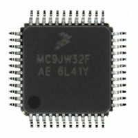
MCHC908JW32FAE Freescale Semiconductor, MCHC908JW32FAE Datasheet - Page 151

MCHC908JW32FAE
Manufacturer Part Number
MCHC908JW32FAE
Description
IC MCU 32K FLASH 8MHZ 48-LQFP
Manufacturer
Freescale Semiconductor
Series
HC08r
Datasheet
1.RD3152MMA7260Q.pdf
(232 pages)
Specifications of MCHC908JW32FAE
Core Processor
HC08
Core Size
8-Bit
Speed
8MHz
Connectivity
SPI, USB
Peripherals
LED, LVD, POR, PWM
Number Of I /o
29
Program Memory Size
32KB (32K x 8)
Program Memory Type
FLASH
Ram Size
1K x 8
Voltage - Supply (vcc/vdd)
3.5 V ~ 5.5 V
Oscillator Type
Internal
Operating Temperature
0°C ~ 70°C
Package / Case
48-LQFP
Controller Family/series
HC08
No. Of I/o's
48
Ram Memory Size
1KB
Cpu Speed
8MHz
No. Of Timers
1
Embedded Interface Type
SPI
Rohs Compliant
Yes
Processor Series
HC08JW
Core
HC08
Data Bus Width
8 bit
Data Ram Size
1 KB
Interface Type
SPI, USB
Number Of Programmable I/os
29
Number Of Timers
2
Maximum Operating Temperature
+ 70 C
Mounting Style
SMD/SMT
Development Tools By Supplier
FSICEBASE, DEMO908GZ60E, M68EML08GZE, KITUSBSPIDGLEVME, KITUSBSPIEVME, KIT33810EKEVME
Minimum Operating Temperature
0 C
Lead Free Status / RoHS Status
Lead free / RoHS Compliant
Eeprom Size
-
Data Converters
-
Lead Free Status / Rohs Status
Details
Available stocks
Company
Part Number
Manufacturer
Quantity
Price
Company:
Part Number:
MCHC908JW32FAE
Manufacturer:
Freescale Semiconductor
Quantity:
10 000
Part Number:
MCHC908JW32FAE
Manufacturer:
FREESCALE
Quantity:
20 000
11.3.4.1 Configuration Process
All USB devices must be configured before used. The host will configure the device according to the
configuration process defined by the USB specification 2.0 Chapter 9. During the process most of the
USB commands issued by the host are responded automatically except GET_DESCRIPTOR,
SYNC_FRAME, vendor specific and class specific commands where user interaction is required. These
are known as the user commands. The number of configurations and interfaces supported is limited by
the module. This module can support a single configuration and maximum of two interfaces. No alternate
setting is allowed.
Upon the reception of the user commands, no module level decoding is done instead user is notified by
the SETUP flag and TFRC_OUT flag. User can then decode the command through the dedicated 8-byte
endpoint 0 buffer. For instance, when a valid GET_DESCRIPTOR command is detected, user is notified
by the SETUP, TFRC_OUT flag and DVALID_OUT flag. User should decode the command via the 8-byte
endpoint 0 OUT buffer. Corresponding return descriptor is written to the endpoint 0 IN buffer 8 bytes at a
time. By setting the DVALID_IN bit, the data is sent to the host in the next IN packet. Otherwise, the
module will return NAK to all IN packet. If ACK is not returned from the host, the data is re-sent
automatically in the next IN packet until ACK is returned from the host, then transfer complete flag
TFRC_IN is set, the next 8 bytes of data can be written to the endpoint 0 IN buffer. The process continues
until the requested descriptor is sent completely.
11.3.4.2 Control Endpoint 0
Endpoint 0 is always treated as control endpoint. It has eight bytes dedicated buffer for device transmit
(IN packet) and eight bytes dedicated buffer for device receive (OUT packet). Most of the host requests
is handled by the requestor processor excepts the class/vendor specified request, GET_DESCRIPTOR
request and the SYNC_FRAME request. If the user is notified by the module about the arrival of such
requests, user can decode the request command by reading the endpoint 0 data register.
The SETUP flag will be set if the 8-byte setup packet is received without CRC/Token/EOP error for
Vendor/Class/SetDescriptor/SynchFrame commands only.
11.3.5 Endpoint Controller
The module has four independent endpoint controllers that managed the data transfer between CPU and
the USB host. Each of these endpoint can be configured to either one of the two modes - bulk or interrupt.
Freescale Semiconductor
Please note the module will return ACK to all valid SETUP packet. No
software attention is required.
Endpoint 0 buffer and endpoint 0 data size register (DSIZE) will be updated
on every incoming SETUP packet. However, SETUP or TFRC_OUT will
not be set unless the SETUP packet is a valid GET_DESCRIPTOR,
SYNC_FRAME or class/vendor specific SETUP command.
For any OUT data received in the 8-byte endpoint OUT buffer, they are only
valid until the start of any SETUP packet addressed to the device, even if
the packet is corrupted the 8-byte OUT buffer may still be overwritten by
this new SETUP packet. There is no indication of the corruption built into
this module.
MC68HC908JW32 Data Sheet, Rev. 6
NOTE
NOTE
USB Module Architecture
151


