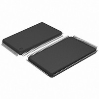
AT91SAM7SE32-AU Atmel, AT91SAM7SE32-AU Datasheet - Page 652

AT91SAM7SE32-AU
Manufacturer Part Number
AT91SAM7SE32-AU
Description
MCU ARM 32K HS FLASH 128-LQFP
Manufacturer
Atmel
Series
AT91SAMr
Specifications of AT91SAM7SE32-AU
Core Processor
ARM7
Core Size
16/32-Bit
Speed
55MHz
Connectivity
EBI/EMI, I²C, SPI, SSC, UART/USART, USB
Peripherals
Brown-out Detect/Reset, POR, PWM, WDT
Number Of I /o
88
Program Memory Size
32KB (32K x 8)
Program Memory Type
FLASH
Ram Size
8K x 8
Voltage - Supply (vcc/vdd)
1.65 V ~ 1.95 V
Data Converters
A/D 8x10b
Oscillator Type
Internal
Operating Temperature
-40°C ~ 85°C
Package / Case
128-LQFP
Controller Family/series
AT91SAM7xxxx
No. Of I/o's
88
Ram Memory Size
8KB
Cpu Speed
48MHz
No. Of Timers
3
Rohs Compliant
Yes
Processor Series
AT91SAMx
Core
ARM7TDMI
Data Bus Width
32 bit
Data Ram Size
8 KB
Interface Type
EBI, SPI, TWI, USART
Maximum Clock Frequency
55 MHz
Number Of Programmable I/os
88
Number Of Timers
3
Maximum Operating Temperature
+ 85 C
Mounting Style
SMD/SMT
3rd Party Development Tools
JTRACE-ARM-2M, KSK-AT91SAM7S-PL, MDK-ARM, RL-ARM, ULINK2
Development Tools By Supplier
AT91SAM-ICE, AT91-ISP, AT91SAM7SE-EK
Minimum Operating Temperature
- 40 C
On-chip Adc
10 bit, 8 Channel
For Use With
AT91SAM7SE-EK - EVAL BOARD FOR AT91SAM7SEAT91SAM-ICE - EMULATOR FOR AT91 ARM7/ARM9
Lead Free Status / RoHS Status
Lead free / RoHS Compliant
Eeprom Size
-
Lead Free Status / Rohs Status
Details
Available stocks
Company
Part Number
Manufacturer
Quantity
Price
Company:
Part Number:
AT91SAM7SE32-AU
Manufacturer:
ATMEL
Quantity:
624
Part Number:
AT91SAM7SE32-AU
Manufacturer:
ATMEL/爱特梅尔
Quantity:
20 000
- Current page: 652 of 655
- Download datasheet (8Mb)
vi
AT91SAM7SE512/256/32 Preliminary
30 Debug Unit (DBGU ............................................................................... 301
31 Parallel Input Output Controller (PIO) ................................................ 325
32 Serial Peripheral Interface (SPI) ......................................................... 351
33 Two-wire Interface (TWI) ..................................................................... 377
29.6 Programmable Clock Output Controller .............................................................279
29.7 Programming Sequence ....................................................................................279
29.8 Clock Switching Details .....................................................................................283
29.9 Power Management Controller (PMC) User Interface ......................................286
30.1 Overview ...........................................................................................................301
30.2 Block Diagram ...................................................................................................302
30.3 Product Dependencies ......................................................................................303
30.4 UART Operations ..............................................................................................303
30.5 Debug Unit User Interface ................................................................................310
31.1 Overview ...........................................................................................................325
31.2 Block Diagram ...................................................................................................326
31.3 Product Dependencies ......................................................................................327
31.4 Functional Description .......................................................................................328
31.5 I/O Lines Programming Example ......................................................................332
31.6 PIO User Interface .............................................................................................334
32.1 Overview ...........................................................................................................351
32.2 Block Diagram ...................................................................................................352
32.3 Application Block Diagram ................................................................................352
32.4 Signal Description ............................................................................................353
32.5 Product Dependencies ......................................................................................353
32.6 Functional Description .......................................................................................354
32.7 Serial Peripheral Interface (SPI) User Interface ................................................363
33.1 Overview ...........................................................................................................377
33.2 Block Diagram ...................................................................................................377
33.3 Application Block Diagram ................................................................................378
33.4 I/O Lines Description .........................................................................................378
33.5 Product Dependencies ......................................................................................378
33.6 Functional Description .......................................................................................379
33.7 Master Mode .....................................................................................................380
33.8 Multi-master Mode .............................................................................................385
33.9 Slave Mode .......................................................................................................388
6222B–ATARM–26-Mar-07
Related parts for AT91SAM7SE32-AU
Image
Part Number
Description
Manufacturer
Datasheet
Request
R

Part Number:
Description:
KIT EVAL FOR ARM AT91SAM7S
Manufacturer:
Atmel
Datasheet:

Part Number:
Description:
MCU, MPU & DSP Development Tools KICKSTART KIT ATMEL AT91SAM7S
Manufacturer:
IAR Systems

Part Number:
Description:
DEV KIT FOR AVR/AVR32
Manufacturer:
Atmel
Datasheet:

Part Number:
Description:
INTERVAL AND WIPE/WASH WIPER CONTROL IC WITH DELAY
Manufacturer:
ATMEL Corporation
Datasheet:

Part Number:
Description:
Low-Voltage Voice-Switched IC for Hands-Free Operation
Manufacturer:
ATMEL Corporation
Datasheet:

Part Number:
Description:
MONOLITHIC INTEGRATED FEATUREPHONE CIRCUIT
Manufacturer:
ATMEL Corporation
Datasheet:

Part Number:
Description:
AM-FM Receiver IC U4255BM-M
Manufacturer:
ATMEL Corporation
Datasheet:

Part Number:
Description:
Monolithic Integrated Feature Phone Circuit
Manufacturer:
ATMEL Corporation
Datasheet:

Part Number:
Description:
Multistandard Video-IF and Quasi Parallel Sound Processing
Manufacturer:
ATMEL Corporation
Datasheet:

Part Number:
Description:
High-performance EE PLD
Manufacturer:
ATMEL Corporation
Datasheet:

Part Number:
Description:
8-bit Flash Microcontroller
Manufacturer:
ATMEL Corporation
Datasheet:

Part Number:
Description:
2-Wire Serial EEPROM
Manufacturer:
ATMEL Corporation
Datasheet:


