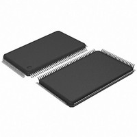
AT91SAM7SE32-AU Atmel, AT91SAM7SE32-AU Datasheet - Page 645

AT91SAM7SE32-AU
Manufacturer Part Number
AT91SAM7SE32-AU
Description
MCU ARM 32K HS FLASH 128-LQFP
Manufacturer
Atmel
Series
AT91SAMr
Specifications of AT91SAM7SE32-AU
Core Processor
ARM7
Core Size
16/32-Bit
Speed
55MHz
Connectivity
EBI/EMI, I²C, SPI, SSC, UART/USART, USB
Peripherals
Brown-out Detect/Reset, POR, PWM, WDT
Number Of I /o
88
Program Memory Size
32KB (32K x 8)
Program Memory Type
FLASH
Ram Size
8K x 8
Voltage - Supply (vcc/vdd)
1.65 V ~ 1.95 V
Data Converters
A/D 8x10b
Oscillator Type
Internal
Operating Temperature
-40°C ~ 85°C
Package / Case
128-LQFP
Controller Family/series
AT91SAM7xxxx
No. Of I/o's
88
Ram Memory Size
8KB
Cpu Speed
48MHz
No. Of Timers
3
Rohs Compliant
Yes
Processor Series
AT91SAMx
Core
ARM7TDMI
Data Bus Width
32 bit
Data Ram Size
8 KB
Interface Type
EBI, SPI, TWI, USART
Maximum Clock Frequency
55 MHz
Number Of Programmable I/os
88
Number Of Timers
3
Maximum Operating Temperature
+ 85 C
Mounting Style
SMD/SMT
3rd Party Development Tools
JTRACE-ARM-2M, KSK-AT91SAM7S-PL, MDK-ARM, RL-ARM, ULINK2
Development Tools By Supplier
AT91SAM-ICE, AT91-ISP, AT91SAM7SE-EK
Minimum Operating Temperature
- 40 C
On-chip Adc
10 bit, 8 Channel
For Use With
AT91SAM7SE-EK - EVAL BOARD FOR AT91SAM7SEAT91SAM-ICE - EMULATOR FOR AT91 ARM7/ARM9
Lead Free Status / RoHS Status
Lead free / RoHS Compliant
Eeprom Size
-
Lead Free Status / Rohs Status
Details
Available stocks
Company
Part Number
Manufacturer
Quantity
Price
Company:
Part Number:
AT91SAM7SE32-AU
Manufacturer:
ATMEL
Quantity:
624
Part Number:
AT91SAM7SE32-AU
Manufacturer:
ATMEL/爱特梅尔
Quantity:
20 000
- Current page: 645 of 655
- Download datasheet (8Mb)
44. Revision History
6222B–ATARM–26-Mar-07
Version
6222A
Version
6222B
Comments
Overview,
“not 5V tolerant”.
INL and DNL updated in
“Features”
Section 7.1 ”ARM7TDMI
Section 7.8 ”Peripheral DMA Controller”
Section 7.5 ”Static Memory Controller”
operations
Clock Generator, Removed information on capacitor load value in
Connections” Figure 28-2 ”Typical Crystal Connection” on page
DBGU, Debug Unit Chip ID Register,
internal RAM size and
added descriptions for CAP7, AT91SAM7AQxx series and CAP11
EBI,
NAND Flash column, added notes to table for SDRAM, NAND FLash and references to app notes.
Figure 21-1 ”Organization of the External Bus Interface”
Section 21.7.6.1 ”Hardware Configuration”
Section 21.7.7.1 ”Hardware Configuration”
Electrical Characteristics,
Section 40.4.3 ”Crystal Characteristics”
Table 40-12, “XIN Clock Electrical Characteristics”
Section 40.7 ”ADC Characteristics”
“Transfer
INL and DNL updated in
Section 40.8.4 ”SMC
page 624
Figure 40-8 ”SMC Signals in Memory Interface Mode”
SMC timings updated to be concordant with signals listed in
Section 40.8.6 ”Embedded Flash Characteristics”
States (VDDCORE = 1.65V)”
Table 40-20, “Master Clock Waveform
Table 40-10, “Main Oscillator Characteristics”
Table 40-7, “Power Consumption for Different Modes”
Table 40-32, “Embedded Flash Wait States (VDDCORE = 1.65V)”
Comments
First issue: Preliminary
Table 21-3, “EBI Pins and External Static Device Connections,” on page
Characteristics”. Reference to Data Converter Terminology added below table.
and in the following two figures.
Section 6.1 ”JTAG Port
on page 2, Fully Static Operation: added up to 55 MHz at 1.8V and 85°C worst case conditions
Section 7.6 ”SDRAM Controller”
Signals”,A25 Address line changed to A22.
“ARCH: Architecture Identifier” on page 323
Section 10.14 ”Analog-to-Digital Converter” on page 42
Section 10.14 ”Analog-to-Digital Converter” on page 42
Processor”, Runs at up to 55 MHz, providing 0.9 MIPS/MHz (core supplied with 1.8V)
and added
Pins”,
INL and DNL updated and Absolute accuracy added to
“SRAMSIZ: Internal SRAM Size” on page 322
Parameters”, updated w/V
Multiple device adaptability: compliant w/PSRAM in synchronous
TCHXIN and TCHLXIN updated, TCLCH and TCHCL added to
PDC priority list added.
Section 6.3 ”Reset
Table 40-33, “Embedded Flash Wait States (VDDCORE = 1.8V)”
A25 removed from CFRNW in CompactFlash
A25 removed from CFRNW in CompactFlash True IDE
AT91SAM7SE512/256/32 Preliminary
added schematic in footnote to C
updated. Note added t
Mobile SDRAM controller added to SDRAMC description
and
and
DDM and DDP pins must be left floating.
Figure 40-2 ”XIN Clock Timing”
SDCK is not multiplexed with PIO
Figure 40-9 ”SM Signals in LCD Interface Mode”
Pin”,
Table 40-25
274, updated, CL1 and CL2 labels removed.
Table 40-25 on page 622
Section 6.5 ”SDCK
DDCORE
footnote
updated bin values for 0x60 and 0xF0, and
Section 28.3.1 ”Main Oscillator
oTable 40-32, “Embedded Flash Wait
= 1.8V, Max = 55 MHz
thru
(2)
Table
140, I/O[8:15] bits added in
added.
L
and C
updated w/AT91SAM7L
40-28.
Pin”, removed statement:
LEXT
has been added.
thru
Table 40-19,
symbols
Table 40-28 on
Change
Request
Ref.
3826
4005
3924
3833
review
3282
3861
3828
3369
3807
3742/3743/
3852
3924
4044/3836
3966
4005
4044/3836
3924
3868
3829
review
Change
Request
Ref.
645
Related parts for AT91SAM7SE32-AU
Image
Part Number
Description
Manufacturer
Datasheet
Request
R

Part Number:
Description:
KIT EVAL FOR ARM AT91SAM7S
Manufacturer:
Atmel
Datasheet:

Part Number:
Description:
MCU, MPU & DSP Development Tools KICKSTART KIT ATMEL AT91SAM7S
Manufacturer:
IAR Systems

Part Number:
Description:
DEV KIT FOR AVR/AVR32
Manufacturer:
Atmel
Datasheet:

Part Number:
Description:
INTERVAL AND WIPE/WASH WIPER CONTROL IC WITH DELAY
Manufacturer:
ATMEL Corporation
Datasheet:

Part Number:
Description:
Low-Voltage Voice-Switched IC for Hands-Free Operation
Manufacturer:
ATMEL Corporation
Datasheet:

Part Number:
Description:
MONOLITHIC INTEGRATED FEATUREPHONE CIRCUIT
Manufacturer:
ATMEL Corporation
Datasheet:

Part Number:
Description:
AM-FM Receiver IC U4255BM-M
Manufacturer:
ATMEL Corporation
Datasheet:

Part Number:
Description:
Monolithic Integrated Feature Phone Circuit
Manufacturer:
ATMEL Corporation
Datasheet:

Part Number:
Description:
Multistandard Video-IF and Quasi Parallel Sound Processing
Manufacturer:
ATMEL Corporation
Datasheet:

Part Number:
Description:
High-performance EE PLD
Manufacturer:
ATMEL Corporation
Datasheet:

Part Number:
Description:
8-bit Flash Microcontroller
Manufacturer:
ATMEL Corporation
Datasheet:

Part Number:
Description:
2-Wire Serial EEPROM
Manufacturer:
ATMEL Corporation
Datasheet:


