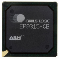
EP9315-CB Cirrus Logic Inc, EP9315-CB Datasheet - Page 277

EP9315-CB
Manufacturer Part Number
EP9315-CB
Description
IC ARM920T MCU 200MHZ 352-PBGA
Manufacturer
Cirrus Logic Inc
Series
EP9r
Specifications of EP9315-CB
Core Processor
ARM9
Core Size
16/32-Bit
Speed
200MHz
Connectivity
EBI/EMI, EIDE, Ethernet, I²C, IrDA, Keypad/Touchscreen, PCMCIA, SPI, UART/USART, USB
Peripherals
AC'97, DMA, I²:S, LCD, LED, MaverickKey, POR, PWM, WDT
Number Of I /o
16
Program Memory Type
ROMless
Ram Size
32K x 8
Voltage - Supply (vcc/vdd)
1.65 V ~ 3.6 V
Data Converters
A/D 8x12b
Oscillator Type
External
Operating Temperature
0°C ~ 70°C
Package / Case
352-BGA
Processor Series
EP93xx
Core
ARM920T
Data Bus Width
32 bit
3rd Party Development Tools
MDK-ARM, RL-ARM, ULINK2
Development Tools By Supplier
EDB9315A-Z
For Use With
598-1144 - KIT DEVELOPMENT EP9315 ARM9
Lead Free Status / RoHS Status
Contains lead / RoHS non-compliant
Eeprom Size
-
Program Memory Size
-
Lead Free Status / Rohs Status
No
Other names
598-1261
Available stocks
Company
Part Number
Manufacturer
Quantity
Price
Part Number:
EP9315-CBZ
Manufacturer:
CIRRUS
Quantity:
20 000
- Current page: 277 of 824
- Download datasheet (13Mb)
DS785UM1
8.6.1 Breshenham’s Algorithm Line Draw
8.6 Register Usage
Since some registers have different meanings based on the type of transfer being performed,
the next section will give the use and meaning of the register during the various graphics
transfers.
The following sequence describes how to set up the registers that are used for a
Breshenham algorithm line draw:
Note:The word count for this example would be: 6 - 1 = 5 words, since P6 ends in the 6th word.
1. Setup LINEINIT Register
2. Setup LINEPATTERN Register
Address
0x005C
0x006C
0x0058
0x0060
0x0064
0x0068
Write YINIT = 0x800 (2048) and XINIT = 0x800 in the
A. Write desired values to the Pattern (PTRN) and Count (CNT) fields to create solid or
B. For a solid line, write CNT = 0xF and PTRN = 0xFFFF to the
C. For a pattern of 8 ‘on’ pixels and 8 ‘off’ pixels, write CNT = 0xF and PTRN = 0x00FF
The word count takes into account the whole pixel, not just the starting location. So,
WIDTH = 0x5 would be written to the
patterned lines. The
value and a 16-bit Pattern (PTRN) that defines 16 pixel on/off patterns for line
functions. CNT specifies the position of the last bit used in the PTRN field starting at
bit 0 of the PTRN field.
register. The solid line will have the color value that is written to the MASK field in
the
to the
written to the MASK field in the
either be transparent as specified by BG = ‘0’ in the
the color value written to the
the
consistent for any line regardless of angle.
“BLOCKMASK”
“BLOCKCTRL”
31
“LINEPATTRN”
Table 8-20. 24 BPP Memory Layout for Destination Image
P1
P2
P3
P5
P6
P7
register. Using DX/DY line draw, the pattern will be more
24 23
register.
“LINEPATTRN”
Copyright 2007 Cirrus Logic
register. The 8 ‘on’ pixels would have the color value that is
“BACKGROUND”
P0
P2
P3
P4
P6
P7
“BLKDESTWIDTH”
“BLOCKMASK”
register contains a 4-bit pattern Count (CNT)
16 15
P0
P1
P3
P4
P5
P7
register as specified by BG = ‘1’ in
register. The 8 ‘off’ pixels would
register.
“LINEINIT”
“BLOCKCTRL”
8 7
“LINEPATTRN”
register.
P0
P1
P2
P4
P5
P6
Graphics Accelerator
EP93xx User’s Guide
register or have
0
8-13
8
Related parts for EP9315-CB
Image
Part Number
Description
Manufacturer
Datasheet
Request
R

Part Number:
Description:
IC ARM9 SOC ENH UNIV 352PBGA
Manufacturer:
Cirrus Logic Inc
Datasheet:

Part Number:
Description:
32-Bit Microcontroller IC
Manufacturer:
Cirrus Logic Inc
Datasheet:

Part Number:
Description:
IC ARM920T MCU 200MHZ 352-PBGA
Manufacturer:
Cirrus Logic Inc
Datasheet:

Part Number:
Description:
MCU, MPU & DSP Development Tools Eval Bd Uni. ARM9 SOC Processor
Manufacturer:
Cirrus Logic Inc
Datasheet:

Part Number:
Description:
IC ARM920T MCU 166MHZ 208-LQFP
Manufacturer:
Cirrus Logic Inc
Datasheet:

Part Number:
Description:
IC ARM920T MCU 200MHZ 352-PBGA
Manufacturer:
Cirrus Logic Inc
Datasheet:

Part Number:
Description:
IC ARM920T MCU 166MHZ 208-LQFP
Manufacturer:
Cirrus Logic Inc
Datasheet:

Part Number:
Description:
Development Kit
Manufacturer:
Cirrus Logic Inc
Datasheet:

Part Number:
Description:
Development Kit
Manufacturer:
Cirrus Logic Inc
Datasheet:

Part Number:
Description:
High-efficiency PFC + Fluorescent Lamp Driver Reference Design
Manufacturer:
Cirrus Logic Inc
Datasheet:

Part Number:
Description:
Development Kit
Manufacturer:
Cirrus Logic Inc
Datasheet:

Part Number:
Description:
Development Kit
Manufacturer:
Cirrus Logic Inc
Datasheet:

Part Number:
Description:
Development Kit
Manufacturer:
Cirrus Logic Inc
Datasheet:

Part Number:
Description:
Ref Bd For Speakerbar MSA & DSP Products
Manufacturer:
Cirrus Logic Inc


