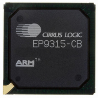
EP9315-CB Cirrus Logic Inc, EP9315-CB Datasheet - Page 20

EP9315-CB
Manufacturer Part Number
EP9315-CB
Description
IC ARM920T MCU 200MHZ 352-PBGA
Manufacturer
Cirrus Logic Inc
Series
EP9r
Specifications of EP9315-CB
Core Processor
ARM9
Core Size
16/32-Bit
Speed
200MHz
Connectivity
EBI/EMI, EIDE, Ethernet, I²C, IrDA, Keypad/Touchscreen, PCMCIA, SPI, UART/USART, USB
Peripherals
AC'97, DMA, I²:S, LCD, LED, MaverickKey, POR, PWM, WDT
Number Of I /o
16
Program Memory Type
ROMless
Ram Size
32K x 8
Voltage - Supply (vcc/vdd)
1.65 V ~ 3.6 V
Data Converters
A/D 8x12b
Oscillator Type
External
Operating Temperature
0°C ~ 70°C
Package / Case
352-BGA
Processor Series
EP93xx
Core
ARM920T
Data Bus Width
32 bit
3rd Party Development Tools
MDK-ARM, RL-ARM, ULINK2
Development Tools By Supplier
EDB9315A-Z
For Use With
598-1144 - KIT DEVELOPMENT EP9315 ARM9
Lead Free Status / RoHS Status
Contains lead / RoHS non-compliant
Eeprom Size
-
Program Memory Size
-
Lead Free Status / Rohs Status
No
Other names
598-1261
Available stocks
Company
Part Number
Manufacturer
Quantity
Price
Part Number:
EP9315-CBZ
Manufacturer:
CIRRUS
Quantity:
20 000
- Current page: 20 of 824
- Download datasheet (13Mb)
EP93xx User’s Guide
xx
Table 11-1. Frame Bandwidth Allocation ....................................................................................................11-7
Table 11-2. OpenHCI Register Addresses................................................................................................11-11
Table 12-1. PCMCIA Address Memory Ranges..........................................................................................12-5
Table 12-2. PCMCIA Pin Usage..................................................................................................................12-5
Table 12-3. Supported 8-Bit Accesses........................................................................................................12-8
Table 12-4. Supported 16-Bit Accesses......................................................................................................12-8
Table 12-5. PCMCIA Legacy Usage ...........................................................................................................12-8
Table 12-6. Accesses to 8-Bit Attribute / Common / IO Memory.................................................................12-9
Table 12-7. Accesses to 16-Bit Attribute / Common / IO Memory...............................................................12-9
Table 12-8. Static Memory Controller (SMC) Register Map......................................................................12-10
Table 13-1. Boot Device Selection ..............................................................................................................13-2
Table 13-2. Address Decoding for Synchronous Memory Domains ...........................................................13-3
Table 13-3. Synchronous Memory Address Decoding................................................................................13-4
Table 13-4. General SDRAM Initialization Sequence .................................................................................13-4
Table 13-5. Mode Register Command Decoding for 32-bit Wide Memory Bus ..........................................13-6
Table 13-6. Sync Memory CAS...................................................................................................................13-7
Table 13-7. Sync Memory RAS, Burst Type, and Write Burst Length.........................................................13-7
Table 13-8. Burst Length.............................................................................................................................13-7
Table 13-9. Chip Select Decoding...............................................................................................................13-9
Table 13-10. Memory Addressing Example ..............................................................................................13-11
Table 13-11. EP93xx SDRAM Address Ranges (16-Bit Wide Data Systems)..........................................13-12
Table 13-12. Address Bits Used for Chip Select .......................................................................................13-17
Table 13-13. Synchronous Memory Controller Registers .........................................................................13-17
Table 13-14. Synchronous Memory Command Encoding.........................................................................13-20
Table 14-1. Receive FIFO Bit Functions .....................................................................................................14-6
Table 14-2. Legal HDLC Mode Configurations .........................................................................................14-10
Table 14-3. HDLC Receive Address Matching Modes..............................................................................14-13
Table 14-4. UART1 Pin Functionality ........................................................................................................14-15
Table 14-5. DeviceCfg Register Bit Functions ..........................................................................................14-15
Table 15-1. UART2 / IrDA Modes ...............................................................................................................15-5
Table 15-2. IonU2 Pin Function...................................................................................................................15-5
Table 16-1. UART3 Pin Functionality ..........................................................................................................16-1
Table 16-2. DeviceCfg Register Bit Functions ............................................................................................16-2
Table 17-1. Bit Values to Select Ir Module ..................................................................................................17-3
Table 17-2. Address Offsets for End-of-Frame Data...................................................................................17-5
Table 17-3. MIR Frame Format...................................................................................................................17-9
Table 17-4. DeviceCfg.IonU2 Pin Function ...............................................................................................17-20
©
Copyright 2007 Cirrus Logic, Inc.
DS785UM1
Related parts for EP9315-CB
Image
Part Number
Description
Manufacturer
Datasheet
Request
R

Part Number:
Description:
IC ARM9 SOC ENH UNIV 352PBGA
Manufacturer:
Cirrus Logic Inc
Datasheet:

Part Number:
Description:
32-Bit Microcontroller IC
Manufacturer:
Cirrus Logic Inc
Datasheet:

Part Number:
Description:
IC ARM920T MCU 200MHZ 352-PBGA
Manufacturer:
Cirrus Logic Inc
Datasheet:

Part Number:
Description:
MCU, MPU & DSP Development Tools Eval Bd Uni. ARM9 SOC Processor
Manufacturer:
Cirrus Logic Inc
Datasheet:

Part Number:
Description:
IC ARM920T MCU 166MHZ 208-LQFP
Manufacturer:
Cirrus Logic Inc
Datasheet:

Part Number:
Description:
IC ARM920T MCU 200MHZ 352-PBGA
Manufacturer:
Cirrus Logic Inc
Datasheet:

Part Number:
Description:
IC ARM920T MCU 166MHZ 208-LQFP
Manufacturer:
Cirrus Logic Inc
Datasheet:

Part Number:
Description:
Development Kit
Manufacturer:
Cirrus Logic Inc
Datasheet:

Part Number:
Description:
Development Kit
Manufacturer:
Cirrus Logic Inc
Datasheet:

Part Number:
Description:
High-efficiency PFC + Fluorescent Lamp Driver Reference Design
Manufacturer:
Cirrus Logic Inc
Datasheet:

Part Number:
Description:
Development Kit
Manufacturer:
Cirrus Logic Inc
Datasheet:

Part Number:
Description:
Development Kit
Manufacturer:
Cirrus Logic Inc
Datasheet:

Part Number:
Description:
Development Kit
Manufacturer:
Cirrus Logic Inc
Datasheet:

Part Number:
Description:
Ref Bd For Speakerbar MSA & DSP Products
Manufacturer:
Cirrus Logic Inc


