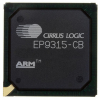
EP9315-CB Cirrus Logic Inc, EP9315-CB Datasheet - Page 121

EP9315-CB
Manufacturer Part Number
EP9315-CB
Description
IC ARM920T MCU 200MHZ 352-PBGA
Manufacturer
Cirrus Logic Inc
Series
EP9r
Specifications of EP9315-CB
Core Processor
ARM9
Core Size
16/32-Bit
Speed
200MHz
Connectivity
EBI/EMI, EIDE, Ethernet, I²C, IrDA, Keypad/Touchscreen, PCMCIA, SPI, UART/USART, USB
Peripherals
AC'97, DMA, I²:S, LCD, LED, MaverickKey, POR, PWM, WDT
Number Of I /o
16
Program Memory Type
ROMless
Ram Size
32K x 8
Voltage - Supply (vcc/vdd)
1.65 V ~ 3.6 V
Data Converters
A/D 8x12b
Oscillator Type
External
Operating Temperature
0°C ~ 70°C
Package / Case
352-BGA
Processor Series
EP93xx
Core
ARM920T
Data Bus Width
32 bit
3rd Party Development Tools
MDK-ARM, RL-ARM, ULINK2
Development Tools By Supplier
EDB9315A-Z
For Use With
598-1144 - KIT DEVELOPMENT EP9315 ARM9
Lead Free Status / RoHS Status
Contains lead / RoHS non-compliant
Eeprom Size
-
Program Memory Size
-
Lead Free Status / Rohs Status
No
Other names
598-1261
Available stocks
Company
Part Number
Manufacturer
Quantity
Price
Part Number:
EP9315-CBZ
Manufacturer:
CIRRUS
Quantity:
20 000
- Current page: 121 of 824
- Download datasheet (13Mb)
DS785UM1
4.1.2.3 Flowchart
Figure 4-1
8. If it is not a Serial Download, attempt to read from SPI Serial Flash (see
9. Attempt to read the “CRUS” or “SURC” HeaderID in ASCII in FLASH memory at FLASH
10.Attempt to read the “CRUS” or “SURC” HeaderID in ASCII in FLASH memory at FLASH
11.Attempt to read the “CRUS” or “SURC” HeaderID in ASCII in memory at 0xC000_0000
12.Attempt to read the “CRUS” or “SURC” HeaderID in ASCII in memory at 0xC000_1000
13.If “CRUS” or “SURC” HeaderID is not found, copy dummy vectors into low SDRAM, and
then follow Steps A, B, C, and D.
Base + 0x0000, and verify the HeaderID. This is read in for each FLASH Chip select
(see
Base + 0x1000, and verify the HeaderID. This is read in for each FLASH Chip select
(see
and 0xF000_0000, and verify the HeaderID. This is read in for SDRAM or SyncFLASH
boot (see
and 0xF000_1000, and verify the HeaderID. This is read in for SDRAM or SyncFLASH
boot (see
then follow Step A.
A. Check if the first 4 bytes from the Serial Flash are equal to “CRUS” or to “SURC” in
B. Read the next 2048 (decimal count) bytes into the Internal Boot Buffer
C. Turn on Green LED
D. Jump to the start of the Internal Boot Buffer
A. Turn on Green LED
B. Jump to the start of FLASH memory plus four bytes
A. Turn on Green LED
B. Jump to the start of FLASH memory
A. Turn on Green LED
B. Jump to memory location 0xC000_0004 or 0xF000_0004
A. Turn on Green LED
B. Jump to memory location 0xC000_0000 or 0xF000_0000
A. Flash Green LED
ASCII, verifying the HeaderID
Figure
Figure
provides a flow chart for operation of the Boot ROM software.
Figure
Figure
4-1), and then follow Steps A and B.
4-1), and then follow Steps A and B.
4-1), and then follow Steps A and B.
4-1), and then follow Steps A and B.
Copyright 2007 Cirrus Logic
EP93xx User’s Guide
Figure
4-1), and
Boot ROM
4-3
4
Related parts for EP9315-CB
Image
Part Number
Description
Manufacturer
Datasheet
Request
R

Part Number:
Description:
IC ARM9 SOC ENH UNIV 352PBGA
Manufacturer:
Cirrus Logic Inc
Datasheet:

Part Number:
Description:
32-Bit Microcontroller IC
Manufacturer:
Cirrus Logic Inc
Datasheet:

Part Number:
Description:
IC ARM920T MCU 200MHZ 352-PBGA
Manufacturer:
Cirrus Logic Inc
Datasheet:

Part Number:
Description:
MCU, MPU & DSP Development Tools Eval Bd Uni. ARM9 SOC Processor
Manufacturer:
Cirrus Logic Inc
Datasheet:

Part Number:
Description:
IC ARM920T MCU 166MHZ 208-LQFP
Manufacturer:
Cirrus Logic Inc
Datasheet:

Part Number:
Description:
IC ARM920T MCU 200MHZ 352-PBGA
Manufacturer:
Cirrus Logic Inc
Datasheet:

Part Number:
Description:
IC ARM920T MCU 166MHZ 208-LQFP
Manufacturer:
Cirrus Logic Inc
Datasheet:

Part Number:
Description:
Development Kit
Manufacturer:
Cirrus Logic Inc
Datasheet:

Part Number:
Description:
Development Kit
Manufacturer:
Cirrus Logic Inc
Datasheet:

Part Number:
Description:
High-efficiency PFC + Fluorescent Lamp Driver Reference Design
Manufacturer:
Cirrus Logic Inc
Datasheet:

Part Number:
Description:
Development Kit
Manufacturer:
Cirrus Logic Inc
Datasheet:

Part Number:
Description:
Development Kit
Manufacturer:
Cirrus Logic Inc
Datasheet:

Part Number:
Description:
Development Kit
Manufacturer:
Cirrus Logic Inc
Datasheet:

Part Number:
Description:
Ref Bd For Speakerbar MSA & DSP Products
Manufacturer:
Cirrus Logic Inc


