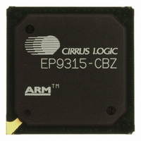
EP9315-CBZ Cirrus Logic Inc, EP9315-CBZ Datasheet - Page 409

EP9315-CBZ
Manufacturer Part Number
EP9315-CBZ
Description
IC ARM9 SOC ENH UNIV 352PBGA
Manufacturer
Cirrus Logic Inc
Series
EP9r
Specifications of EP9315-CBZ
Core Size
16/32-Bit
Core Processor
ARM9
Speed
200MHz
Connectivity
EBI/EMI, EIDE, Ethernet, I²C, IrDA, Keypad/Touchscreen, PCMCIA, SPI, UART/USART, USB
Peripherals
AC'97, DMA, I²:S, LCD, LED, MaverickKey, POR, PWM, WDT
Number Of I /o
16
Program Memory Type
ROMless
Ram Size
32K x 8
Voltage - Supply (vcc/vdd)
1.65 V ~ 3.6 V
Data Converters
A/D 8x12b
Oscillator Type
External
Operating Temperature
0°C ~ 70°C
Package / Case
352-BGA
Controller Family/series
(ARM9)
No. Of I/o's
16
Cpu Speed
200MHz
No. Of Timers
5
Digital Ic Case Style
BGA
Supply Voltage Range
1.65V To 1.94V, 3V To 3.6V
Embedded Interface Type
SPI
Rohs Compliant
Yes
Processor Series
EP93xx
Core
ARM920T
Data Bus Width
32 bit
3rd Party Development Tools
MDK-ARM, RL-ARM, ULINK2
Development Tools By Supplier
EDB9315A-Z
Case
BGA
Dc
06+
Lead Free Status / RoHS Status
Lead free / RoHS Compliant
For Use With
598-1144 - KIT DEVELOPMENT EP9315 ARM9
Eeprom Size
-
Program Memory Size
-
Lead Free Status / Rohs Status
Details
Other names
598-1139
Available stocks
Company
Part Number
Manufacturer
Quantity
Price
Part Number:
EP9315-CBZ
Manufacturer:
CIRRUS
Quantity:
20 000
- Current page: 409 of 824
- Download datasheet (13Mb)
DS785UM1
10.1.10.4 Data Transfer Termination
The DMA Controller terminates a memory-to-memory channel transfer under the following
conditions:
• For a software-triggered M2M transfer, a memory-write is initiated when the 16-byte data
• For transfers involving external devices or SSP/IDE, the DMA memory-write phase is
• For software-triggered transfers which use a single buffer, the transfer is terminated
• For hardware-triggered transfers involving SSP or IDE or external devices without
• For operations involving external devices using a single buffer, the transfer is terminated
bay has been filled (in the case where 16 or more bytes remain to be transferred) or
when it contains the appropriate number of bytes (equal to BCR register value if BCR is
less than 16). The DMA controller drives the DAR_BASEx onto the address bus. This
address can be any aligned byte address. The BCR register decrements by the
appropriate number of bytes. When BCR = 0 then the transfer is complete. If BCR is
greater than zero, another read/write transfer is initiated.
initiated when the data bay contains the byte/half-word/word data, depending on PW
value, that is, peripheral width. The DMA will then drive the DAR_BASEx onto the
address bus and will set the AMBA HSIZE signal in accordance with the PW value.
Once the DMA has received confirmation that the write is done (from HREADY in case
of an internal memory write, or from the SMC acknowledge signal in case of an external
device write), a wait state counter is started. During the count, the hardware request line
is masked, in order to allow the related peripheral to de-assert its request. In the case of
CONTROL.TM = “01” and the external device (which is the destination for the data) is
FIFO-based, it is up to software to program the DAH bit correctly (Destination Address
Hold), so that on successive transfers to the peripheral, the DAR_CURRENTx value will
not increment, thus reflecting the FIFO-nature of the peripheral.
when the BCR register of the active buffer has reached zero. The DONE status bit and
corresponding interrupt (if enabled) are set. In the case of double/multiple buffer
transfers, termination occurs when the BCR registers of both buffer descriptors has
reached zero. The DONE status bit and corresponding interrupt (if enabled) are set.
When the DONE interrupt is set the processor can then write a one to clear the interrupt
before reprogramming the DMA to carry out another M2M transfer.
handshaking signals, the transfer is also terminated when the BCR register of the active
buffer has reached zero. The DONE status bit and corresponding interrupt (if enabled)
are set. When the DONE interrupt is set, the processor can then write a one to clear the
interrupt before reprogramming the DMA to carry out another external DMA transfer.
on the first occurrence of DEOT being asserted by the device or the byte count expiring
for the active buffer. In the case of the DMA receiving a DEOT from the peripheral (which
is aligned to DREQ) the DMA knows that this is the final transfer to be performed. The
DONE status bit and corresponding interrupt (if enabled) are set. In the case of
double/multiple buffer transfers, termination occurs on either the occurrence of the DMA
receiving a DEOT from the device while it is transferring to/from the last buffer (that is,
no other buffer has been set up), or when the BCR registers of both buffer descriptors
has reached zero.
Copyright 2007 Cirrus Logic
EP93xx User’s Guide
DMA Controller
10-15
10
Related parts for EP9315-CBZ
Image
Part Number
Description
Manufacturer
Datasheet
Request
R

Part Number:
Description:
IC ARM920T MCU 200MHZ 352-PBGA
Manufacturer:
Cirrus Logic Inc
Datasheet:

Part Number:
Description:
32-Bit Microcontroller IC
Manufacturer:
Cirrus Logic Inc
Datasheet:

Part Number:
Description:
IC ARM920T MCU 200MHZ 352-PBGA
Manufacturer:
Cirrus Logic Inc
Datasheet:

Part Number:
Description:
MCU, MPU & DSP Development Tools Eval Bd Uni. ARM9 SOC Processor
Manufacturer:
Cirrus Logic Inc
Datasheet:

Part Number:
Description:
Development Kit
Manufacturer:
Cirrus Logic Inc
Datasheet:

Part Number:
Description:
Development Kit
Manufacturer:
Cirrus Logic Inc
Datasheet:

Part Number:
Description:
High-efficiency PFC + Fluorescent Lamp Driver Reference Design
Manufacturer:
Cirrus Logic Inc
Datasheet:

Part Number:
Description:
Development Kit
Manufacturer:
Cirrus Logic Inc
Datasheet:

Part Number:
Description:
Development Kit
Manufacturer:
Cirrus Logic Inc
Datasheet:

Part Number:
Description:
Development Kit
Manufacturer:
Cirrus Logic Inc
Datasheet:

Part Number:
Description:
Development Kit
Manufacturer:
Cirrus Logic Inc
Datasheet:

Part Number:
Description:
Development Kit
Manufacturer:
Cirrus Logic Inc
Datasheet:

Part Number:
Description:
Development Kit
Manufacturer:
Cirrus Logic Inc
Datasheet:

Part Number:
Description:
Ref Bd For Speakerbar MSA & DSP Products
Manufacturer:
Cirrus Logic Inc


