MC9S08DZ60ACLF Freescale Semiconductor, MC9S08DZ60ACLF Datasheet - Page 175
MC9S08DZ60ACLF
Manufacturer Part Number
MC9S08DZ60ACLF
Description
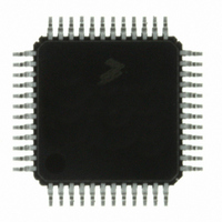
IC MCU 60K FLASH 4K RAM 48-LQFP
Manufacturer
Freescale Semiconductor
Series
HCS08r
Datasheets
1.DEMO9S08DZ60.pdf
(416 pages)
2.EVB9S08DZ60.pdf
(4 pages)
3.MC9S08DZ48AMLF.pdf
(458 pages)
Specifications of MC9S08DZ60ACLF
Core Processor
HCS08
Core Size
8-Bit
Speed
40MHz
Connectivity
CAN, I²C, LIN, SCI, SPI
Peripherals
LVD, POR, PWM, WDT
Number Of I /o
39
Program Memory Size
60KB (60K x 8)
Program Memory Type
FLASH
Eeprom Size
2K x 8
Ram Size
4K x 8
Voltage - Supply (vcc/vdd)
2.7 V ~ 5.5 V
Data Converters
A/D 16x12b
Oscillator Type
External
Operating Temperature
-40°C ~ 85°C
Package / Case
48-LQFP
Processor Series
S08DZ
Core
HCS08
Data Bus Width
8 bit
Data Ram Size
4 KB
Interface Type
CAN, I2C, SCI, SPI
Maximum Clock Frequency
40 MHz
Number Of Programmable I/os
53
Number Of Timers
2
Operating Supply Voltage
5.5 V
Maximum Operating Temperature
+ 85 C
Mounting Style
SMD/SMT
3rd Party Development Tools
EWS08
Development Tools By Supplier
DEMO9S08DZ60
Minimum Operating Temperature
- 40 C
On-chip Adc
12 bit, 24 Channel
For Use With
DEMO9S08DZ60 - BOARD DEMOEVB9S08DZ60 - BOARD EVAL FOR 9S08DZ60
Lead Free Status / RoHS Status
Lead free / RoHS Compliant
Available stocks
Company
Part Number
Manufacturer
Quantity
Price
Company:

Part Number:
MC9S08DZ60ACLF
Manufacturer:
FREESCAL
Quantity:
1 250
Company:
Part Number:
MC9S08DZ60ACLF
Manufacturer:
Freescale Semiconductor
Quantity:
10 000


8.3.5
Freescale Semiconductor
OSCINIT
FTRIM
LOLIE
Field
Field
PLLS
CME
1
0
7
6
5
Reset:
W
R
MCG Control Register 3 (MCGC3)
OSC Initialization — If the external reference clock is selected by ERCLKEN or by the MCG being in FEE, FBE,
PEE, PBE, or BLPE mode, and if EREFS is set, then this bit is set after the initialization cycles of the external
oscillator clock have completed. This bit is only cleared when either EREFS is cleared or when the MCG is in
either FEI, FBI, or BLPI mode and ERCLKEN is cleared.
MCG Fine Trim — Controls the smallest adjustment of the internal reference clock frequency. Setting FTRIM
will increase the period and clearing FTRIM will decrease the period by the smallest amount possible.
If an FTRIM value stored in nonvolatile memory is to be used, it’s the user’s responsibility to copy that value from
the nonvolatile memory location to this register’s FTRIM bit.
Loss of Lock Interrupt Enable — Determines if an interrupt request is made following a loss of lock indication.
The LOLIE bit only has an effect when LOLS is set.
0 No request on loss of lock.
1 Generate an interrupt request on loss of lock.
PLL Select — Controls whether the PLL or FLL is selected. If the PLLS bit is clear, the PLL is disabled in all
modes. If the PLLS is set, the FLL is disabled in all modes.
1 PLL is selected
0 FLL is selected
Clock Monitor Enable — Determines if a reset request is made following a loss of external clock indication. The
CME bit should only be set to a logic 1 when either the MCG is in an operational mode that uses the external
clock (FEE, FBE, PEE, PBE, or BLPE) or the external reference is enabled (ERCLKEN=1 in the MCGC2
register). Whenever the CME bit is set to a logic 1, the value of the RANGE bit in the MCGC2 register should not
be changed.
0 Clock monitor is disabled.
1 Generate a reset request on loss of external clock.
Table 8-6. MCG Status and Control Register Field Descriptions (continued)
LOLIE
7
0
Table 8-7. MCG Control Register 3 Field Descriptions
PLLS
0
6
Figure 8-7. MCG Control Register 3 (MCGC3)
MC9S08DZ128 Series Data Sheet, Rev. 1
CME
0
5
DIV32
0
4
Description
Description
Chapter 8 Multi-Purpose Clock Generator (S08MCGV2)
0
3
0
2
VDIV
0
1
1
0
175
Related parts for MC9S08DZ60ACLF
Image
Part Number
Description
Manufacturer
Datasheet
Request
R

Part Number:
Description:
Manufacturer:
Freescale Semiconductor, Inc
Datasheet:
Part Number:
Description:
Manufacturer:
Freescale Semiconductor, Inc
Datasheet:
Part Number:
Description:
Manufacturer:
Freescale Semiconductor, Inc
Datasheet:
Part Number:
Description:
Manufacturer:
Freescale Semiconductor, Inc
Datasheet:
Part Number:
Description:
Manufacturer:
Freescale Semiconductor, Inc
Datasheet:
Part Number:
Description:
Manufacturer:
Freescale Semiconductor, Inc
Datasheet:
Part Number:
Description:
Manufacturer:
Freescale Semiconductor, Inc
Datasheet:
Part Number:
Description:
Manufacturer:
Freescale Semiconductor, Inc
Datasheet:
Part Number:
Description:
Manufacturer:
Freescale Semiconductor, Inc
Datasheet:
Part Number:
Description:
Manufacturer:
Freescale Semiconductor, Inc
Datasheet:
Part Number:
Description:
Manufacturer:
Freescale Semiconductor, Inc
Datasheet:
Part Number:
Description:
Manufacturer:
Freescale Semiconductor, Inc
Datasheet:
Part Number:
Description:
Manufacturer:
Freescale Semiconductor, Inc
Datasheet:
Part Number:
Description:
Manufacturer:
Freescale Semiconductor, Inc
Datasheet:
Part Number:
Description:
Manufacturer:
Freescale Semiconductor, Inc
Datasheet: