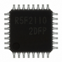
R5F21102DFP#U0 Renesas Electronics America, R5F21102DFP#U0 Datasheet - Page 199

R5F21102DFP#U0
Manufacturer Part Number
R5F21102DFP#U0
Description
IC R8C MCU FLASH 8K 32LQFP
Manufacturer
Renesas Electronics America
Series
M16C™ M16C/R8C/Tiny/10r
Datasheets
1.R5F211A2SPU0.pdf
(300 pages)
2.R5F21102FPU0.pdf
(30 pages)
3.R5F21102FPU0.pdf
(201 pages)
Specifications of R5F21102DFP#U0
Core Processor
R8C
Core Size
16-Bit
Speed
16MHz
Connectivity
SIO, UART/USART
Peripherals
LED, WDT
Number Of I /o
22
Program Memory Size
8KB (8K x 8)
Program Memory Type
FLASH
Ram Size
512 x 8
Voltage - Supply (vcc/vdd)
2.7 V ~ 5.5 V
Data Converters
A/D 8x10b
Oscillator Type
Internal
Operating Temperature
-40°C ~ 85°C
Package / Case
32-LQFP
For Use With
R0K521134S000BE - KIT EVAL STARTER FOR R8C/13R0E521134EPB00 - KIT EMULATOR PROBE FOR PC7501R0E521134CPE00 - EMULATOR COMPACT R8C/13
Lead Free Status / RoHS Status
Lead free / RoHS Compliant
Eeprom Size
-
Available stocks
Company
Part Number
Manufacturer
Quantity
Price
- Current page: 199 of 201
- Download datasheet (2Mb)
Rev.
1.20 Jan.27.2006
Date
REVISION HISTORY
Page
127
129
130
133
137
113
116
117
118
119
132
136
147
153
156
158
162
166
176
____________
14.7 Output Impedance of Sensor under A/D Conversion added
Figure 15.1 Programmable I/O Ports (1); NOTES: 1 added
Figure 15.2 Programmable I/O Ports (2); NOTES: 1 added
Figure 15.3 Programmable I/O Ports (3); NOTES: 1 added
Figure 15.4 Programmable I/O Ports (4); NOTES: 3 added
Table 15.20 Port P3
Table 15.22 Port P4
Table 15.23 Port X
Setting value: External input to X
CM1: “1”
Table 16.2 Recommended Operating Conditions; NOTES: 1, 2, 3 revised
Table 16.3 A/D Conversion Characteristics;
“A/D operation clock frequency”
NOTES: 1, 2, 3, 4 revised
Table 16.4 Flash Memory (Program ROM) Electrical Characteristics;
“Data retention duration”
“Topr”
NOTES: 2 added
Measuring condition of byte program time and block erase time deleted
Table 16.6 Electrical Characteristics (1) [V
“P1
Table 16.7 Electrical Characteristics (2) [V
NOTES: 1, 2 revised
Measuring condition: Stop mode “Topr = 25 °C” added
Table 16.13 Electrical Characteristics (3) [V
“P1
Table 16.14 Electrical Characteristics (4) [V
NOTES: 1, 2 revised
Measuring condition: Stop mode “Topr = 25 °C” added
Figure 17.4 FMR1 and FMR4;
Flash memory control register 4 NOTES: 2 “Other than this period, this bit is set to
“0”.” revised
Figure 17.11 Block Erase Command (When Using Erase-suspend Function);
“Write ‘D0
“Write ‘D0
Figure 17.12 Full Status Check and Handling Procedure for Each Error revised
Table 17.7 Pin Functions (Flash Memory Standard Serial I/O Mode);
RESET: revised
19.1.1 Stop Mode
“Use the next program to enter stop mode.” added
“• Example of entering stop mode”
“Program Example” deleted
19.3.1 Oscillation Stop Detection Function
“Since the oscillation stop ... is 2 MHz or below, ...”
“Since the oscillation stop ... is below 2 MHz, ...” revised
Appendix figure 2.2 Connecting examples with M16C Flash Starter (M3A-0806);
Pulled up added
NOTES: 1 revised
0
0
to P1
to P1
“Ambient temperature” revised
16
16
7
7
’ to the uppermost block address”
’ to the any block address” revised
Except X
Except X
“0”, CM0: “0”
IN
3
5
/P4
/INT
/INT
OUT
OUT
_______
_______
C-7
6
”
”
, X
3
0
/TC
Setting; Bit: “PD3_3”
OUT
“Data hold time” revised
“Except P1
“Except P1
“1”, Feedback resistance: “OFF”
Description
IN
R8C/10 Group Hardware Manual
/P4
Setting; Bit: “PD3_1”
IN
7
pin, “H” output from X
“A/D operating clock frequency” revised
Setting;
Summary
“• Program of entering stop mode”
0
0
to P1
to P1
CC
CC
CC
CC
=5V];
=5V]
=3V]
=3V]
7
7
, X
, X
OUT
OUT
“PD4_5”
” revised
” revised
“PD3_3”
OUT
pin;
“ON”
Related parts for R5F21102DFP#U0
Image
Part Number
Description
Manufacturer
Datasheet
Request
R

Part Number:
Description:
KIT STARTER FOR M16C/29
Manufacturer:
Renesas Electronics America
Datasheet:

Part Number:
Description:
KIT STARTER FOR R8C/2D
Manufacturer:
Renesas Electronics America
Datasheet:

Part Number:
Description:
R0K33062P STARTER KIT
Manufacturer:
Renesas Electronics America
Datasheet:

Part Number:
Description:
KIT STARTER FOR R8C/23 E8A
Manufacturer:
Renesas Electronics America
Datasheet:

Part Number:
Description:
KIT STARTER FOR R8C/25
Manufacturer:
Renesas Electronics America
Datasheet:

Part Number:
Description:
KIT STARTER H8S2456 SHARPE DSPLY
Manufacturer:
Renesas Electronics America
Datasheet:

Part Number:
Description:
KIT STARTER FOR R8C38C
Manufacturer:
Renesas Electronics America
Datasheet:

Part Number:
Description:
KIT STARTER FOR R8C35C
Manufacturer:
Renesas Electronics America
Datasheet:

Part Number:
Description:
KIT STARTER FOR R8CL3AC+LCD APPS
Manufacturer:
Renesas Electronics America
Datasheet:

Part Number:
Description:
KIT STARTER FOR RX610
Manufacturer:
Renesas Electronics America
Datasheet:

Part Number:
Description:
KIT STARTER FOR R32C/118
Manufacturer:
Renesas Electronics America
Datasheet:

Part Number:
Description:
KIT DEV RSK-R8C/26-29
Manufacturer:
Renesas Electronics America
Datasheet:

Part Number:
Description:
KIT STARTER FOR SH7124
Manufacturer:
Renesas Electronics America
Datasheet:

Part Number:
Description:
KIT STARTER FOR H8SX/1622
Manufacturer:
Renesas Electronics America
Datasheet:

Part Number:
Description:
KIT DEV FOR SH7203
Manufacturer:
Renesas Electronics America
Datasheet:


