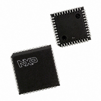
P87C591VFA/00,512 NXP Semiconductors, P87C591VFA/00,512 Datasheet - Page 32

P87C591VFA/00,512
Manufacturer Part Number
P87C591VFA/00,512
Description
IC 80C51 MCU 16K OTP 44-PLCC
Manufacturer
NXP Semiconductors
Series
87Cr
Datasheet
1.P87C591VFA00512.pdf
(160 pages)
Specifications of P87C591VFA/00,512
Core Processor
8051
Core Size
8-Bit
Speed
12MHz
Connectivity
CAN, EBI/EMI, I²C, UART/USART
Peripherals
POR, PWM, WDT
Number Of I /o
32
Program Memory Size
16KB (16K x 8)
Program Memory Type
OTP
Ram Size
512 x 8
Voltage - Supply (vcc/vdd)
4.75 V ~ 5.25 V
Data Converters
A/D 6x10b
Oscillator Type
Internal
Operating Temperature
-40°C ~ 85°C
Package / Case
44-PLCC
Processor Series
P87C5x
Core
80C51
Data Bus Width
8 bit
Data Ram Size
512 B
Interface Type
CAN, I2C, UART
Maximum Clock Frequency
12 MHz
Number Of Programmable I/os
32
Number Of Timers
3
Maximum Operating Temperature
+ 85 C
Mounting Style
SMD/SMT
3rd Party Development Tools
PK51, CA51, A51, ULINK2
Minimum Operating Temperature
- 40 C
On-chip Adc
10 bit, 6 Channel
Lead Free Status / RoHS Status
Lead free / RoHS Compliant
Eeprom Size
-
Lead Free Status / Rohs Status
Details
Other names
568-1256-5
935268182512
P87C591VFAA
935268182512
P87C591VFAA
Available stocks
Company
Part Number
Manufacturer
Quantity
Price
Company:
Part Number:
P87C591VFA/00,512
Manufacturer:
TI
Quantity:
8
Company:
Part Number:
P87C591VFA/00,512
Manufacturer:
NXP Semiconductors
Quantity:
10 000
Philips Semiconductors
12.5
12.5.1
Detection of a set Reset Mode bit results in aborting the current transmission / reception of a message and entering the
Reset Mode. On the ‘1’-to-’0’ transition of the Reset Mode bit, the CAN controller returns to the mode defined within the
Mode Register.
Table 12 Reset mode configuration
“X” means that the values of these registers or bits are not influenced.
2000 Jul 26
ADDR.
Single-chip 8-bit microcontroller with CAN controller
0
1
2
3
4
5
6
7
CAN Registers
R
ESET
Mode
Command
Status
Interrupt
Interrupt Enable
Rx Interrupt Level
Bus Timing 0
Bus Timing 1
REGISTER
V
ALUES
MOD.7
MOD.6
MOD.5
MOD.4
MOD.3
MOD.2
MOD.1
MOD.0
CMR.7-5
CMR.4
CMR.3
CMR.2
CMR.1
CMR.0
SR.7
SR.6
SR.5
SR.4
SR.3
SR.2
SR.1
SR.0
IR.7
IR.6
IR.5
IR.4
IR.3
IR.2
IR.1
IR.0
IER.7
IER.6
IER.5
IER.4
IER.3
IER.2
IER.1
IER.0
-
BTR0.7
BTR0.6
BTR0.5
BTR0.4
BTR0.3
BTR0.2
BTR0.1
BTR0.0
BTR1.7
BTR1.6
BTR1.5
BTR1.4
BTR1.3
BTR1.2
BTR1.1
BTR1.0
BIT
TM
-
RPM
SM
-
STM
LOM
RM
-
SRR
CDO
RRB
AT
TR
BS
ES
TS
RS
TCS
TBS
DOS
RBS
BEI
ALI
EPI
WUI
DOI
EI
TI
RI
BEIE
ALIE
EPIE
WUIE
DOIE
EIE
TIE
RIE
RIL
SJW.1
SJW.0
BRP.5
BRP.4 BRP.3
BRP.2
BRP.1 BRP.0
SAM
TSEG2.2
TSEG2.1
TSEG2.0
TSEG1.3
TSEG1.2
TSEG1.1
TSEG1.0
SYMBOL
Test Mode
-
Receive Polarity Mode
Sleep Mode
-
Self Test Mode
Listen Only Mode
Reset Mode
-
Self Reception Request
Clear Data Overrun
Release Receive Buffer
Abort Transmission
Transmission Request
Bus Status
Error Status
Transmit Status
Receive Status
Transmission Complete Status
Transmit Buffer Status
Data Overrun Status
Receive Buffer Status
Bus Error Interrupt
Arbitration Lost Interrupt
Error Passive Interrupt
Wake-Up Interrupt
Data Overrun Interrupt
Error Warning Interrupt
Transmit Interrupt
Receive Interrupt
Bus Error Interrupt Enable
Arbitr. Lost Interrupt Enable
Error Passive Interrupt
Wake-Up Interrupt Enable
Data Overrun Interrupt Enable
Error Warning Interrupt Enable
Transmit Interrupt Enable
Receive Interrupt Enable
Rx Interrupt Level
Synchronization Jump Width 1
Synchronization Jump Width 0
Baud Rate Prescaler 5
Baud Rate Prescaler 4
Baud Rate Prescaler 3
Baud Rate Prescaler 2
Baud Rate Prescaler 1
Baud Rate Prescaler 0
Sampling
Time Segment 2.2
Time Segment 2.1
Time Segment 2.0
Time Segment 1.3
Time Segment 1.2
Time Segment 1.1
Time Segment 1.0
32
NAME
0 (disabled)
X (reserved)
0 (active low)
0 (wake-up)
0 (reserved)
0 (normal)
0 (normal)
1 (present)
0 (reserved)
0 (absent)
0 (no action)
0 (no action)
0 (absent)
0 (absent)
0 (Bus-On)
0 (ok)
1 (wait idle)
1 (wait idle)
1 (complete)
1 (released)
0 (absent)
0 (empty)
0 (reset)
0 (reset)
0 (reset)
0 (reset)
0 (reset)
0 (reset)
0 (reset)
0 (reset)
X no change
X no change
X no change
X no change
X no change
X no change
X no change
X no change
00000000b
X no change
X no change
X no change
X no change
X no change
X no change
X no change
X no change
X no change
X no change
X no change
X no change
X no change
X no change
X no change
X no change
HARDWARE
RESET BY
Preliminary Specification
0 (disabled)
X (reserved)
0 (active high)
0 (wake-up)
0 (reserved)
X no change
X no change
1 (present)
0 (reserved)
0 (absent)
0 (no action)
0 (no action)
0 (absent)
0 (absent)
0 (reset)
0 (reset)
0 (reset)
0 (reset)
0 (reset)
X no change (1)
0 (reset)
0 (reset)
X no change (1)
0 (reset)
0 (reset)
0 (reset)
0 (reset)
X no change
0 (reset)
0 (reset)
X no change
X no change
X no change
X no change
X no change
X no change
X no change
X no change
X no change
X no change
X no change
X no change
X no change
X no change
X no change
X no change
X no change
X no change
X no change
X no change
X no change
X no change
X no change
X no change
X no change
SETTING MOD.0 BY
DUE TO BUS-OFF
SOFTWARE OR
P8xC591


